
Touching monolithic flasher - buzzer circuit diagram

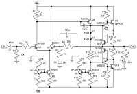
The circuit utilizes a combination of logic gates and oscillators to create a simple touch-sensitive LED flasher. The RS flip-flop, composed of two NAND gates (N1 and N2), is responsible for storing the state of the touch input. The inputs at pins 8 and 13 serve as the trigger points for the flip-flop; when one of these inputs receives a high signal, the output at pin Q will change state.
The controlled oscillator, formed by N3 and N4, is a key component that generates a square wave signal. This oscillator is enabled only when the output of the RS flip-flop (pin Q of N1) is high. The configuration of N3 allows it to function as an astable multivibrator, producing a continuous oscillation that drives the LED. The frequency of oscillation, and thus the flashing rate of the LED, is influenced by the values of the resistors and capacitors connected to N3.
The touch-sensitive pad TP1 acts as a manual input device. When a finger bridges the pad, it creates a path to ground or to a high voltage, depending on the circuit design. This action triggers the RS flip-flop, which changes state and enables the oscillator. The resulting output is a visually observable LED flash, providing immediate feedback to the user.
The design can be further enhanced by adjusting component values to modify the flashing frequency, adding additional LEDs for visual effects, or incorporating debounce circuitry to ensure stable operation when the touch pad is activated. Overall, this circuit exemplifies a straightforward application of digital logic and oscillator principles to create an interactive electronic device.In the circuit, N1, N2 constitute the RS flip-flop, and the trigger end is pin 8 and 13; N3, N4 form the controlled oscillator, only when N3`s pin 1 is high, the oscillator works. When the finger touching pad TP1 is bridging, N1 output`s pin turns to high level, the oscillator will oscillate, then the LED flashes, and the flash frequency is determined by..
🔗 External reference
Related Circuits
Here is a deluxe version of the simple charge rate limiter, using the same idea but with the ability to charge two packs simultaneously from a single wall charger. For circuit description and parts list, see the simple charger...
To configure the amplifier, set resistor R1 to its maximum value and resistor R12 to zero. After this adjustment, power on the amplifier. Adjust R1 until the measured output offset is between 30 mV and 100 mV. Once this...
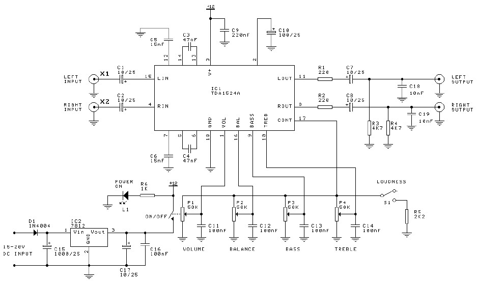
Preamplifier and tone control circuit based on the TDA1524A. The tone control circuit module is included in this preamplifier circuit, allowing for direct connection of the output channels to a stereo power audio amplifier circuit. This RIAA stereo preamplifier...
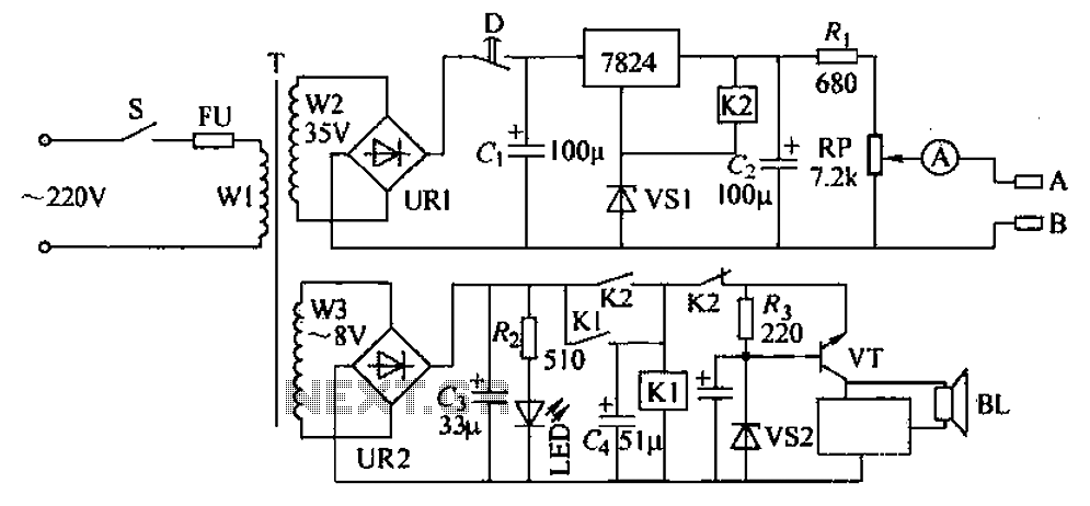
Currently, there is an increasing number of patients suffering from osteoarthritis, which causes significant discomfort. To alleviate this suffering and help patients return to normal life, a therapeutic circuit is utilized. This circuit applies direct current through electrodes coated...
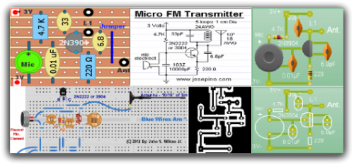
Radio-Circuits has elevated the standard with this website. Unlike any other circuit site on the internet, they have compiled ten of the most popular FM transmitter circuits. Radio-Circuits provides a comprehensive collection of FM transmitter circuits, showcasing a variety of...
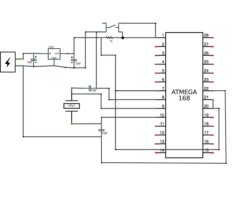
ATMega168 or ATMega328 microcontroller chip with Arduino bootloader (the one on your Arduino can be used temporarily) costs between $4.00 and $5.50. It is advisable to purchase an unbootloaded chip from Mouser for a lower price or a bootloaded...