
Osteoarthritis treatment circuit

The circuit operates by activating the AC 220V voltage, which causes the transformer windings (W2 and W3) to generate 35V AC and 8V AC. The 8V AC voltage is processed through bridge rectifier UR2 and filter capacitor C3, illuminating an LED. The timer (D) is set to determine the treatment duration. The 35V AC voltage is converted to direct current via bridge rectifier UR1 and regulated by the three-terminal regulator, which outputs a steady voltage after filtering through capacitors. This regulated output is then limited by resistors R1 and RP before being applied to electrodes A and B on the patient's affected area. Simultaneously, relay K2 is activated, opening its normally closed contacts and closing its normally open contacts, while relay K1 is energized, closing its normally open contacts. Upon completion of the treatment duration, the timer (D) disconnects, cutting off the input voltage to the 7824 regulator. This releases relay K2, reverting its contacts to the normally closed state, while the contacts of K1 and K2 provide voltage to an alarm circuit, activating a speaker (BL) to signal the end of the treatment session.
The described circuit employs a systematic approach to deliver therapeutic electrical stimulation to patients suffering from osteoarthritis. The integration of a timing mechanism allows for controlled treatment sessions, while the use of relays ensures that the system can provide audible feedback when treatment concludes. By utilizing a combination of AC to DC conversion, voltage regulation, and relay control, the circuit effectively enhances patient care and contributes to the management of osteoarthritis symptoms. The design ensures safety and reliability, which are crucial in medical applications, while also facilitating ease of use for healthcare providers. At present, more and more patients with osteoarthritis, osteoarthritis to relieve the tremendous suffering to the patient, so that patients return to normal life. In this case the circuit is applied to the patient through the DC coated with the drug diseased part two electrodes, can effectively alleviate the suffering of patients, play a supporting role in the treatment. (1) The circuit osteoarthritis therapy device circuit from the power circuit, a timing circuit, the current regulating circuit, control circuit and power circuit from the power switch S, the power transformer T, rectifier diode bridge UR1, UR2, filter capacitor C1, C2, 7824 three-terminal integrated voltage regulator, steady voltage diode vs] and so on, as shown in Figure 24-8.
(2) circuit works turned on the AC 220V voltage, the transformer windings W2 and W3 T secondary winding side respectively generate 35V AC voltage and the AC voltage of 8V. 8V AC voltage UR2 after bridge rectifier and filter c3, the LED lights. Turn the timer D (set treatment time), AC 35V electrical voltage into direct current through the bridge rectifier UR1 after pressure by controlling the contact of the timer D input terminal points plus three terminal regulator block, then by cl filtering and 7824, VS1 steady after pressure from the regulator output block outputs 7824, after R1 and RP limiting, by electrode a and B applied to the diseased part of the patient.
And this at the same time, the relay K2 pull its normally closed contacts K2 off, normally open contact K2 is turned on, the relay Kl is energized, normally open contact Kl on. When the treatment time, the timer D contact off, cut off regulator block 7824 input operating voltage, relay K2 release, its normally open contact K2 off, normally closed contact K2 connected, both ends of the G voltage through the normally open contacts Kl K1 and K2 to provide work for the music alarm circuits as voltage, so that the circuit, music alarm sound emitted from the speaker BL, suggesting that the time has come to treat patients.
Related Circuits
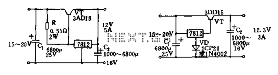
Expand integrated three-terminal regulator block circuit output current method The integrated three-terminal regulator is a versatile component commonly used in power supply circuits to provide a stable output voltage. This regulator typically consists of three terminals: input, output, and ground....
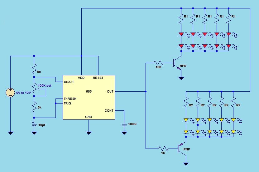
This project utilizes a 555 timer integrated circuit (IC) in an 8-pin configuration to control multiple LEDs. It is designed for quick assembly and allows for the adjustment of timing functions. The circuit employs a 555 timer in astable mode,...
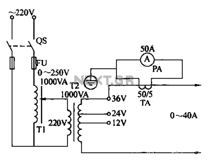
Electricians sometimes use overcurrent relays, thermal relays, and other devices to perform periodic overcurrent checks with a current generator. A secure running lights transformer, voltage regulator, and meter can be constructed using a small electric current generator. The homemade...
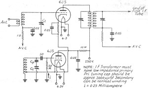
In 2011, designing a frequency converter circuit typically involves selecting an integrated circuit (IC) that meets specific requirements regarding gain and mixer spurious products, along with adding a couple of filters and a power supply. Often, the oscillator is...
This circuit is designed to detect whether the load of a battery charger or plug-in adapter is properly connected. The load may consist of a set of batteries needing charging or any other device that operates on low DC...

A telephone utilizes electric current to transmit sound information between homes. During a conversation, a steady electric current flows through both telephones, which share this current. As one person speaks into their telephone's microphone, the current drawn from the...