
Toy Train rail detector circuit

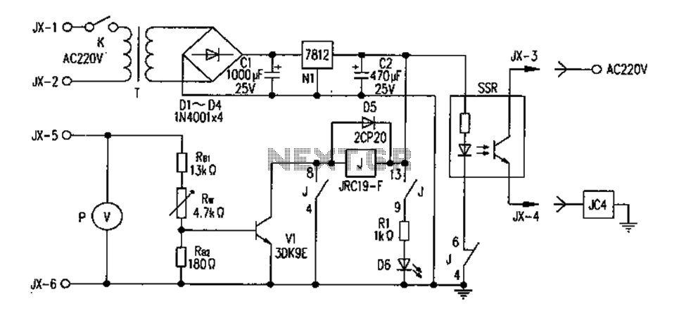
This circuit serves as a signal interface between a transformer and a track for train detection applications. The connection points JP1, JP2, and JP3 facilitate the integration of the transformer and the track with the circuit. The transformer is connected at JP1, while JP2 serves as a link to the control circuitry, and JP3 connects to the track rails.
The circuit is designed to recognize a TTL "High" signal when the current on the track exceeds 2 mA, which is sufficient for typical LED consumption, ensuring reliable operation. The design utilizes four diodes (D1 to D4) configured in an anti-parallel arrangement, allowing current flow in both directions through the circuit. This configuration is essential for applications where the direction of current may change, such as in a train detection system.
The diodes specified are 1N4001, which can handle the necessary current and voltage ratings. A resistor (R1) of approximately 40 Ohms is included to limit the current flowing through the circuit, protecting sensitive components from excessive current. Two additional resistors (R2 and R3), each rated at 10 kOhm, are used in the circuit likely for biasing or pull-up functions.
Optocouplers OC1 and OC2, either CNY17 or PC702, provide electrical isolation between the track and the control circuitry. This isolation is crucial to prevent any high voltages or transients on the track from affecting the control logic. The output of the optocouplers can be connected to an inverter (IC1: 74xx04) which may be used to invert the signal for further processing.
An OR gate (IC2: 74xx02) is employed at the output stage to ensure that a "High" signal is always produced when either side of the train is detected. This allows for a clear indication of train presence regardless of the direction of travel, facilitating the design of signaling or detection systems. The overall design is robust and suitable for applications in model train control systems or similar projects requiring reliable train detection.This circuit must be used between the drive voltage of such a transformer and track. On JP1, the transformer is connected to JP2, the rails are connected to JP3, is a TTL "High" position when there is a tax on the trail is more of 2mA, but given the average LED more consumption, this should not be a problem. Works through a circuit voltage of 1.4 volts over the diodes, which are anti-parallel so that the circuit in both directions to use.
This is always one of the two optocouplers ratified. Making it possible to find the inverters to see which side the train, of course, may be indicated by LEDs. But I had no purpose, so the OR gate at the end so I always have a "high" you which side the train also ascents.
D1 to D4: 1N4001 R1: 40 Ohms (or near) R2, R3: 10 kOhm OC1, OC2: CNY17 or PC702 IC1: 74xx04 IC2: 74xx02 🔗 External reference
Related Circuits
Toyota MR2 Exterior Lights Wiring Diagram Manual PDF Download. The Toyota MR2 Exterior Lights Wiring Diagram Manual provides a comprehensive guide for understanding the wiring configurations associated with the exterior lighting system of the Toyota MR2 model. This manual is...
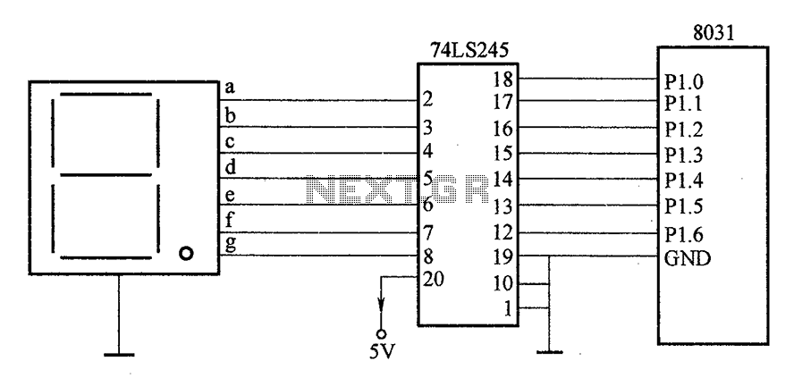
After the SCM execution, the Pl output port connects to the bidirectional input of 74LS245 driver chips. This driver operates during each phase of digital control, based on the information from the Pl port. The purpose is to convert...
The NE555 circuit implementation involves various connections and configurations. The circuit is designed with a supply voltage (Vcc) of +11V. The input terminal (pin 3) serves as a reset pin, and the relay and motor components are integrated into...
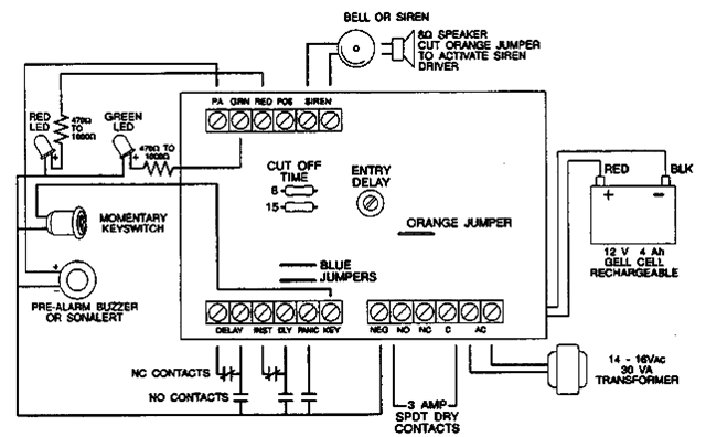
The following alarm circuit is designed with features that may be suitable for residential and commercial alarm system applications. It has a 12V and 1.5A regulated power supply. Furthermore, this residential alarm circuit also includes a delay circuit, a...
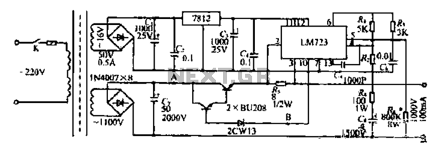
The FM302E-I-type FM transmitter exciter is utilized in Japan's NEC HPB a 1210 motherboard. It features direct carrier frequency modulation, phase-locked frequency stabilization, and frequency synthesis. The preamplifier (BLF-177 FET) is directly driven by an actuator, achieving a maximum...
This document presents plans for a simple ground plane antenna that is effective in the FM band (88-108 MHz). It is constructed from a small plastic disk. The 6 x 6 loop antenna, designed by Graham Maynard, is highlighted...