
A volt DC power supply circuit

The NE555 timer IC is a versatile component widely used in various applications, including timing, pulse generation, and oscillator functions. The circuit typically operates in either astable or monostable mode, depending on the configuration of external resistors and capacitors connected to the timer.
In the astable mode, the NE555 generates a continuous square wave output, with the frequency and duty cycle determined by the resistor and capacitor values. The output is taken from pin 3, which can drive various loads, such as LEDs, relays, or other electronic devices. The reset functionality on pin 4 allows for interrupting the timer operation, while the threshold and trigger pins (pins 6 and 2, respectively) are used to set the timing intervals.
In the monostable mode, the NE555 produces a single output pulse in response to a trigger signal. The duration of the pulse is determined by the resistor and capacitor connected to the timing pins. This mode is commonly used for applications requiring a timed response, such as in delay circuits or pulse-width modulation.
The power supply for the NE555 circuit is typically provided through pin 8 (Vcc), and it is essential to ensure that the voltage levels are within the specified range for reliable operation. The output pin (pin 3) can source or sink current to drive connected components, making it a critical part of the circuit design.
Overall, the NE555 timer IC is a robust and flexible component that can be adapted for various electronic applications, making it a staple in circuit design for both hobbyists and professionals. Proper understanding of its configuration and operation is crucial for effective implementation in any project. By the old I *, jh;, ililiiit; NE555 circuit implementation and other child member, NE555 1yj complex I end (6) feet. Set bit Vr: {2) feet Ding electrical equipment connected s servant K indole road by J4L/ipi border value +11, etc., the pair of the two ports Ib E just equal to the supply voltage Vcc 1- 2. That is set to catch the f Min quiet 1/3Vt: e, r small reset explain false 2/3Vce. ijc ~ mc to tie Cui il: Huang Zhong like hanging system h1E55 of special planing plant clamor servant.
j: Electric Slap ln], mountain riuh L2 na ashamed River. IC (NE555) WJ (6) feet for the electricity supplier -I. LIj input terminal (3) is also low reset pin diode rely V r Kazuya fI. Relay Pi release like confusion, motor Ml] + rotating chain l-.wj hit l ~ iH travel outside walking XK2 move, throw out a {r XK2 later. XK 2 WJ touch. Closed .1C Wd (2) feet potential Ov, s {j little bit Shua Zha two rubbish] who l/3Vce more t [C Phi Chad (3) feet 1 electric amidine change i/t;., Following.
I-what measures the foundation f contact manifold station, electrical} Jl {sneeze to fil/iJ wire transfer .lU village l ifLiXK2 touch. Zengduanqiongdan. Foot electric complex to l 2vce. when the back (6) feet lu shovel also address door vce, da 1; reset electrical shaving lc - bu, wh ic output terminal (j) i loyal electronic information .h {; sit, machines continue unpredictable rotating .i old block j {sleep stroke .li7r share skewer ge xk1 h soil 1 foot.
goblets journal servant crossed period fiii electric half fi -}, chih dust mountain rrm rotation
Related Circuits
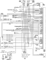
The electrical wiring diagram for the 1993 VW Passat includes the Engine Control Module, Automatic Control Unit, and Automatic Solenoid. This diagram illustrates the connections and wiring between various components of the vehicle's system, such as the multi-function switch,...
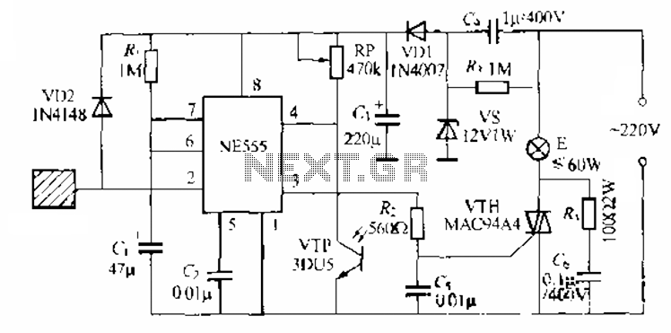
The circuit utilizes a NE553 automatic light sensor composed of 55 groups, allowing lights to turn on when individuals are present and turn off when they leave. The power supply includes VD1, vS, and C, with a 12V DC...
For several years, a rear fog lamp has been mandatory for trailers and caravans to improve visibility in foggy conditions. When this fog lamp is activated, the fog lamp of the towing vehicle must be turned off to prevent...
A simple test circuit designed for troubleshooting audio and radio equipment. It can inject a square wave signal rich in harmonics or be used with headphones as an audio tracer. A single-pole double-throw switch is utilized to toggle between...
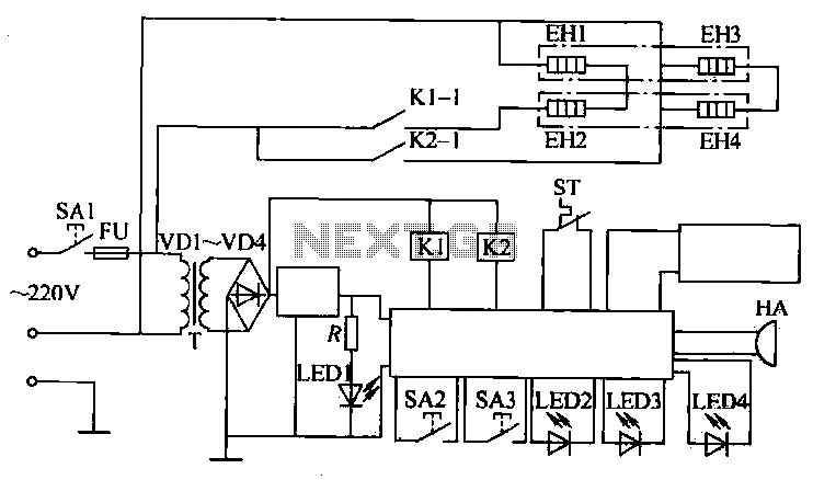
The circuit operates by activating switch SA1, which powers a 220V transformer that converts AC voltage to DC through a bridge rectifier, supplying power to the computer control panel. The temperature for cooking food is set on this control...
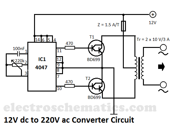
This DIY 12V to 220V voltage converter is built with the CMOS 4047, which serves as the main component of this compact voltage converter that transforms 12V DC into 220V AC. The 4047 is configured as an astable multivibrator,...