
Traffic Lights Beginner Arduino Project

To create a functional traffic light circuit on a breadboard, the following components are required: three LEDs (red, yellow, green), two additional smaller LEDs (red and green for pedestrian signals), buttons, a 1 kΩ resistor, and jumper wires.
The main traffic light configuration consists of the three larger LEDs arranged vertically. The red LED is positioned at the topmost location on the breadboard, followed by the yellow LED in the middle, and the green LED at the bottom. Each LED should be connected to a suitable current-limiting resistor (typically around 220Ω to 330Ω) to prevent excessive current from damaging the LEDs. The anodes (longer leads) of the LEDs should be connected to the positive voltage supply, while the cathodes (shorter leads) are connected to the ground through the resistors.
The pedestrian crossing signals are represented by the smaller red and green LEDs. The red pedestrian signal should be placed directly above the green pedestrian signal. Similar to the main traffic lights, these LEDs also require current-limiting resistors connected in series.
The buttons serve as manual control mechanisms for the traffic lights and pedestrian signals. Each button should be connected with at least two pin holes of space on either side to accommodate the necessary wiring and resistors. The configuration involves connecting one terminal of each button to the positive voltage supply and the other terminal to the respective LED circuit. The 1 kΩ resistor should be placed between the button terminal connected to the LED circuit and the negative rail on the breadboard, ensuring that pressing the button completes the circuit and activates the corresponding LED.
Connections should be made using jumper wires to establish links between the LEDs, buttons, and the power supply. It is essential to verify the polarity of the LEDs and ensure that all connections are secure to facilitate proper operation of the traffic light system. This setup will allow for the demonstration of traffic light sequences and pedestrian signal activation in a compact and visually intuitive manner.Setup the lights on the breadboard like a traffic light. Red on top, then yellow, and then green. The small red and green are the pedestrian crossing signals. Again red on top and green just below. Put the buttons in so you have at least 2 pin holes space to add the wires and resistors. Place the 1kohm resistor between one side of the button and t he negative run on the breadboard. 🔗 External reference
Related Circuits
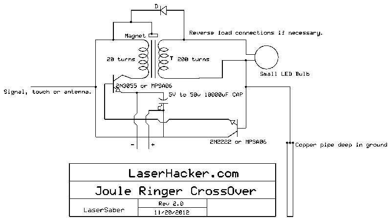
The conversion of a circuit from NPN to PNP configuration is in progress, along with a switch in polarity. Parts are being ordered for this modification. The conversion from an NPN to a PNP transistor involves several key changes in...
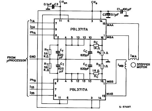
The PBL3717A stepper motor driver is a monolithic integrated circuit that controls and drives one phase of a bipolar stepper motor utilizing chopper control for phase current regulation. Current levels can be selected in three increments using two logic...
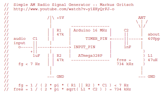
Markus constructed a software AM radio transmitter utilizing an Arduino. The audio signal is supplied to the ADC input via a decoupling capacitor. A PWM output pin directly controls a capacitor-inductor circuit connected to an antenna. The schematic and...
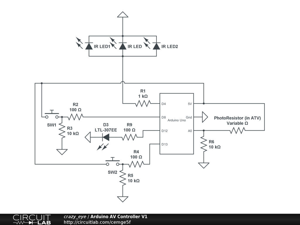
Arduino Event-Driven Universal AV Remote May 1st, 2013. Turn everything on with Airplay. The project involves the development of an Arduino-based universal remote control designed to manage various audio-visual (AV) components through an event-driven architecture. This remote utilizes Airplay...
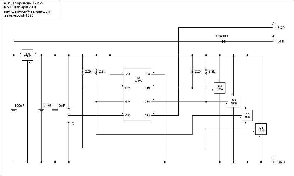
Just a handful of components builds an 8-pin microcontroller based circuit for temperature logging via a serial port; small, fast, and acceptably accurate. More: provides real-time data to your computer via serial port, interfaces up to four DS1820 temperature...
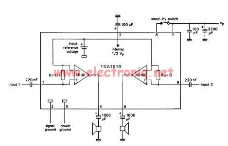
The TDA1519 circuit can deliver 2x6 watts of output power. The TDA1519 is an integrated class-B dual output amplifier housed in a 9-lead single in-line (SIL) plastic medium power package, primarily developed for car radio applications. The TDA1519 amplifier is...