
Train Horn

The train horn circuit based on the NE556 IC is designed to produce a sound similar to that of a traditional train horn. The NE556 is a dual timer IC that combines the functionality of two 555 timers, allowing for versatile configuration in generating audio signals. The circuit requires additional amplification to achieve the desired loudness, necessitating the integration of an audio amplifier. The use of operational amplifiers such as the LM3900 in conjunction with the NE556 enhances the output capabilities, providing a larger voltage swing and improved sound quality.
The components involved in the construction of the train horn circuit include resistors (R1 through R7), capacitors (C1 through C6), and the NE556 IC. The values of the resistors and capacitors are critical for determining the frequency and amplitude of the output sound. For instance, the values of R1 (68K), R2 (2.2K), and C1 (22nF) will set the timing characteristics of the oscillation, which is crucial for producing the horn's sound profile.
In parallel, the audio microphone preamplifier circuit utilizes the LM358 dual op-amp to amplify signals from an electret microphone. This circuit is essential for capturing sound input before amplification, ensuring that the audio signal is strong enough for further processing. The components list for this circuit includes resistors and capacitors, which are selected to optimize the gain and frequency response of the preamplifier.
The 80W amplifier circuit based on the TDA7295 is designed to deliver high-quality audio output with minimal distortion. The TDA7295 is well-regarded for its low noise operation, making it suitable for applications where sound clarity is paramount. The schematic diagram and PCB layout facilitate the construction of this amplifier, ensuring that users can build an efficient audio system.
Finally, the DC motor speed controller circuit, which employs the NE556 as a PWM generator, allows for precise control of motor speed. By varying the duty cycle of the PWM signal, the motor speed can be adjusted to meet specific requirements. This feature is particularly useful in applications where motor performance needs to be finely tuned. The integration of two oscillators within a single IC package simplifies the design and reduces component count, making it an efficient solution for motor control applications.Train Horn Circuit Diagram based IC NE556. The circuit is quite simple and easy to built, also it is inexpensive. With this circuit design, it will not give high output power, so you need to add audio amplifier to make this train horn circuit louder. Imagine for a moment that you are driving down the road in your truck and it has been a long and d ifficult day. All you want now is to make it home and get to sleep. As you are traveling down the highway you notice a car that is swerving for a moment and inside. This is an easy, low cost and easy built circuit of an electronic horn which is designed close to quadruple op-amp IC LM3900 (IC1). IC LM3900 has four independent operational-amplifiers (A1 through A4) having a large output voltage swing.
It is able to operate at up to 32V DC. The 1st op-amp (A1) is designed. The following diagram is the schematic diagram fo Car Horn, you may try this circuit for your car modification. :) Components List: R1 = 68K R2 = 2K2 R3 = 56K R4 = 3K3 R5, R6 = 4K7 R7 = 10K Pot/trimpot C1, C2 = 22nF C3, C5 = 100nF C4 = 1nF C6 = 220 µF/25V IC1, IC2 =.
Here the simple audio mic pre amplifier circuit based on single IC LM358. The circuit is very simple, inexpensive and easy to built. Component Parts List: R1, R3, R4 = 10K R2 = 1K R5 = 100K-1M Potensiometer C1 = 0. 1uF C2 = 4. 7uF/16V IC1 = LM358 dual op-amp single supply Mic = Electret Microphone. Below is a 80W amplifier circuit is constructed by using a power IC TDA7295. With a very simple design, makes this circuit very easy to build. TDA7295 has many features to support your audio system, the most important is that the IC has very low distortion and very low noise feature. Schematic diagram: PCB Layout:. This is the schematic diagram of DC motor speed controller circuit. The circuit applies two oscillators/timers which are connected as a Pulse Width Modulator (PWM). The timer chip which applied in this circuit will be an nmos dual timer/oscillator NE556. This timer IC has two 555 timers in a single 14-pin IC package. One 555. 🔗 External reference
Related Circuits
The individual has been engaged in garden railroading for just over a year, utilizing skills from various hobbies. They have designed and built two scratch-built bridges and nearly 100 trestle bents to support a 200-foot main line. Their interests...
The main power supply to the system must be a regulated 12 volts DC with a minimum input from the train control AC or DC power supply of 13.5 VAC connected to pos 3 and 4 of the rectifier...

This circuit is a module for a diesel and horn train system. It is constructed using a 555 timer IC and several operational amplifiers (op-amps). The circuit serves as a complete system for the horn function. The main power...
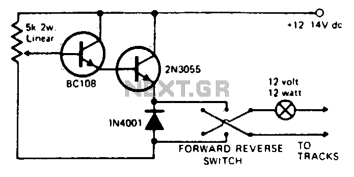
Any NPN small signal transistor can replace the BC 108 shown in the circuit. Similarly, any appropriate NPN power transistor can substitute for the 2N3055. It is essential to mount the output transistor on a suitable heat sink. Short...
A relay is an electrically operated switch that utilizes a coil to create magnetism, which closes the contacts of the switch. In automotive applications, a 12V signal through the coil allows 12V to flow through the switch contacts. The...
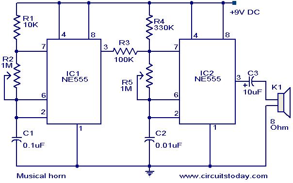
This document outlines a straightforward circuit diagram for a musical horn utilizing two NE555 integrated circuits (ICs). Both ICs are configured as astable multivibrators. The output from the first multivibrator is connected to the discharge pin (pin 7) of...