
Musical horn circuit

The circuit employs two NE555 timers, which are versatile and widely used in various applications due to their reliability and ease of use. In this setup, each NE555 operates in its astable mode, producing continuous square wave signals. The frequency of oscillation for each NE555 can be adjusted by selecting appropriate resistor and capacitor values connected to their timing pins.
The first NE555 timer generates a square wave signal that serves as a trigger for the second NE555 timer. This configuration allows for the modulation of the output frequency of the second NE555 based on the frequency of the first. By adjusting the resistors and capacitors in the circuit, different musical tones can be produced, which can be amplified and used to drive a speaker or buzzer, effectively creating a musical horn.
In practical implementation, the circuit requires careful consideration of component values to ensure that the desired frequency range and tonal quality are achieved. Additionally, the power supply voltage for the NE555 ICs should be selected to match the specifications provided in the datasheet, typically ranging from 4.5V to 15V, to ensure optimal performance. Proper decoupling capacitors should also be included near the power supply pins of the ICs to minimize noise and improve stability.
Overall, this simple circuit design demonstrates the use of NE555 timers in creating sound-producing devices, showcasing their versatility in electronic applications.Here is a simple circuit diagram of a simple musical horn using two NE555 ICs. Two ICs are wired as astable mutivibrators. The output of first multivibrator is given to the discharge (pin 7) of the second astable multivibrator. The combined effect of the astable multivibrators produces a musical tone at the output. 🔗 External reference
Related Circuits

This is a design circuit diagram of a versatile FM transmitter. This circuit does not include a coil and is simple and easy to assemble. It operates based on gate logic concepts. The circuit features a buffer gate N1...
The schematic diagram of the MS Decoder may appear complex, but it is relatively straightforward. Initially, both the Mid and Side signals are buffered using unity gain inverting buffers, which are constructed around IC1b and IC2b. This buffering serves...

The circuit for the Digital Tachometer/RPM Counter consists of a few components. They should be connected according to the provided circuit diagram. The PIC used is on a demonstration board, meaning the clock, power, and ground pins are already...
To extend the measurement range of an available ADC (analog to digital converter), autoranging can be utilized. If implemented on multiplexed input, this... Autoranging is a technique employed in electronic measurement systems to automatically adjust the range of an analog-to-digital...
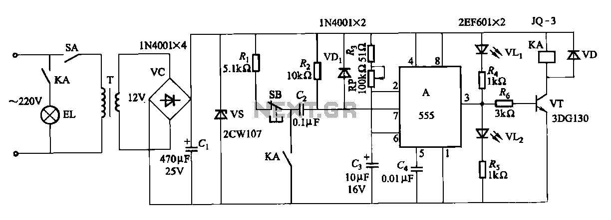
The second circuit for darkroom time exposure utilizes a 555 timer integrated circuit (IC A) for timing functions. A relay controlled by the circuit regulates the exposure light source. The exposure time can be adjusted using potentiometer RP, allowing...
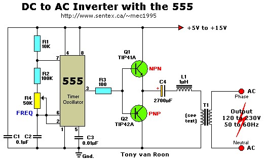
This simple 12V DC to 220V AC inverter circuit generates an AC output at line frequency and voltage. The 555 timer is configured as a low-frequency oscillator, adjustable over the frequency range of 50 to 60 Hz via the...