
Broadband high frequency amplifying circuit

The broadband high-frequency amplifying circuit is engineered to amplify signals within a wide frequency range effectively. The inclusion of a high-frequency matching transformer is critical, as it provides impedance matching between the input signal and the transistor amplifier. This matching is essential for maximizing power transfer and minimizing signal reflection, which is particularly important in high-frequency applications.
The circuit typically employs a transistor, such as a bipolar junction transistor (BJT) or a field-effect transistor (FET), for amplification. The transistor's high input impedance allows it to receive signals without significantly loading the preceding stage, which is beneficial when interfacing with other circuit elements or sources.
The emitter capacitor connected to the transistor VT1 plays a dual role; it not only stabilizes the operating point of the transistor but also allows high-frequency signals to pass while blocking low-frequency signals, thus enhancing the circuit's frequency response. The inductor in conjunction with the capacitor forms a resonant circuit that can further improve the gain and bandwidth at specific frequencies.
The collector of the transistor VT2 is designed to accommodate the amplified high-frequency output. This output can be utilized in various applications, such as RF communication systems, signal processing, and other electronic devices requiring robust amplification of high-frequency signals.
Overall, this broadband high-frequency amplifying circuit is a versatile and essential component in modern electronic design, capable of delivering reliable performance across a broad spectrum of frequencies while maintaining signal integrity and minimizing distortion. Broadband high frequency amplifying circuit Shown as a broadband high frequency amplifying circuit, and is mainly composed of a high-frequency matching transformer amplifying t ransistor and the like, can be used to put a large high-frequency signals. High-frequency signal input of the amplifier circuit is to facilitate the matching transformer input signal transistor amplifier with high input impedance matching feature, but also has a wide frequency band characteristics, VT1 emitter capacitor and inductor are for the collector VT2 compensate the high frequency signal and mining take approach.
Related Circuits
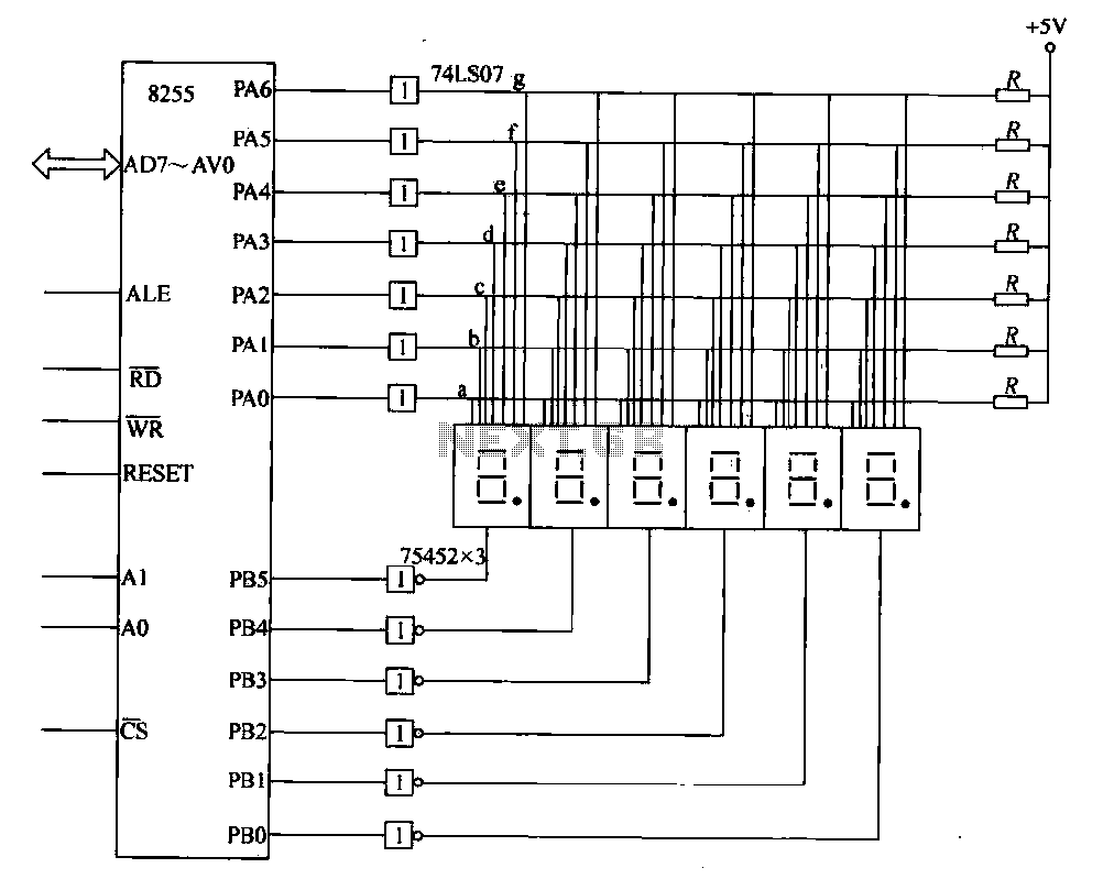
This circuit demonstrates a typical six-digit dynamic display configuration. It utilizes the PA 8255 for display output code and the PB port for bit selection code. The display buffer is designated as DISBUF, which processes the hexadecimal number obtained...
This circuit is a high voltage regulator that features foldback current limiter protection. It utilizes the LM10 comparator along with a voltage reference in its core design. The high voltage regulator circuit is designed to maintain a stable output voltage...
The FM modulator circuit, which utilizes frequency modulation, is constructed using a Motorola MC1648P oscillator. Two varactors, specifically Motorola MV-209, are employed to modulate the frequency of the oscillator. A 5000-ohm potentiometer is incorporated to bias the varactors for...
The following circuit illustrates a Bass-Treble Tone Control Circuit electronic diagram based on the LM1035N integrated circuit (IC). Features include a 0.3 Vrms input level, 80 dB signal noise ratio, 75 dB volume control, ±15 dB typical tone control,...
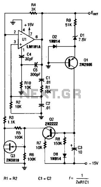
For variable-frequency operation, Rl and R2 can be replaced by a dual potentiometer. In electronic circuits that require variable-frequency operation, the use of a dual potentiometer as a replacement for resistors Rl and R2 can provide enhanced functionality and flexibility....
The wire connected to the 5V pin is linked to the positive pins of the breadboard, which are not connected to any other components. There are no additional connections on the positive column. While this may seem like a...