
transformer Single pole AC to DC conversion circuit

To create a functional remote control light switch using the existing two-wire configuration, a solution must be devised to provide a continuous 3.3V DC supply for the microcontroller and radio components. Given the absence of a neutral wire in the switch panel, one potential approach is to utilize a capacitive power supply circuit, which can draw energy from the live wire and convert it into a usable DC voltage.
The proposed circuit would consist of a capacitive dropper circuit that can be connected to the live wire. This circuit would include a capacitor in series with a resistor, which allows for the charging of the capacitor during the positive half-cycle of the AC voltage. A diode should be incorporated to rectify the AC input, allowing current to flow in one direction and charging the capacitor. The capacitor would then discharge through a voltage regulator to provide a stable 3.3V DC output for the microcontroller and radio.
To ensure that the microcontroller and radio receive a continuous supply, a large capacitor should be used to store enough charge during each cycle. Additionally, a low-dropout voltage regulator (LDO) can be employed to maintain a consistent output voltage, compensating for any ripple that may occur due to the charging and discharging cycles of the capacitor.
It is also crucial to include appropriate safety measures, such as fuses or circuit breakers, to protect the circuit from overcurrent situations. Proper insulation and housing must be considered to prevent any accidental contact with live components.
In summary, the implementation of a capacitive power supply circuit with rectification and regulation will allow for the conversion of the available AC voltage from the live wire into a continuous 3.3V DC supply, thereby enabling the operation of the remote control light switch and its associated electronics.A remote control light switch that fits into the existing light switch panel. And to power up the electronics that would requires a 3. 3V DC supply. The problem is, the panel has only two wires inside - 1. Live and 2. wires that goes to the light bulb. The neutral lines is not routed through the panel box. The capacitor got charged by the positive and negative cycle, I suppose. But I want a continuous supply of DC for the microcontroller/radio, I am not sure how to modify that. 🔗 External reference
Related Circuits
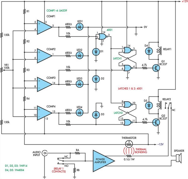
When the voltage on the non-inverting input of each comparator exceeds the voltage at its inverting input, the output transitions to a high state, activating the corresponding LED. NOR gate latches are connected to the outputs of the third...

Connect the components, ensuring to pay attention to the connections for the transistor. The 22-ohm load resistor and thermistor should be connected in a manner that allows for good thermal contact. Note: If using the Light Application Adapter, REFIN-...
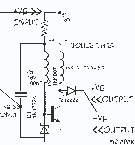
This circuit diagram is provided for those interested. It is a small circuit that takes an input of 1.5 volts and outputs 120 volts. The circuit in question is a voltage step-up converter, commonly referred to as a boost converter....
This AC motor speed controller can handle most universal type (brushed) AC motors and other loads up to about 250W. It works in much the same way as a light dimmer circuit; by chopping part of the AC waveform...
Have you ever witnessed the stairs to an upper story in your home transform into a waterfall? Or perhaps you have returned home to find your aquarium fish attempting to swim across the carpet? For your sake, it is...
The circuit is designed around a 555 oscillator/timer, providing two distinct time periods. The longer time period can be adjusted between approximately 1 to 10 minutes, while the shorter time period is fixed at around three seconds. The operation...