
Transformerless Power Supply Circuit-Ouputs 5 Volt DC

The transformerless power supply circuit is designed to convert AC voltage directly to a lower DC voltage without the use of a transformer. This type of circuit is particularly useful in applications where space and cost are critical factors. The circuit typically consists of a few key components, including a rectifier, a filtering capacitor, and a voltage regulator.
The input AC voltage is usually derived from a standard mains supply, which can range from 110V to 240V, depending on the region. The circuit begins with a series resistor that limits the current flowing into the circuit. This resistor is crucial as it protects the subsequent components from excessive current that could cause damage.
Following the resistor, a diode rectifier is employed to convert the AC voltage to pulsating DC. A common choice for this application is a 1N4007 diode, which can handle the necessary voltage and current ratings. After rectification, the output is still not pure DC; therefore, a smoothing capacitor is added to the circuit. This capacitor helps to reduce the ripple voltage, providing a more stable DC output.
To achieve a precise output voltage of 5 volts, a voltage regulator may be implemented. A low-dropout (LDO) regulator, such as the LM7805, can be used to ensure that the output voltage remains stable under varying load conditions. This regulator requires input voltage to be at least a couple of volts higher than the desired output voltage to function correctly.
It is important to note that transformerless power supplies are limited in terms of current output, typically providing only a few hundred milliamps. As such, they are not suitable for high-power applications but work well for low-power devices like LEDs, small sensors, or microcontrollers.
When designing a transformerless power supply, safety precautions must be taken into account, as the circuit is directly connected to the mains voltage. Proper insulation, component ratings, and circuit enclosures should be implemented to prevent electric shock hazards. Additionally, the circuit should be tested under controlled conditions to ensure it operates safely and reliably.A simple transformerless power supply circuit with diagram and schematics that gives 5 volts dc output.This is a low cost,low current power supply circuit suitable for simple applications like power an LED.. 🔗 External reference
Related Circuits
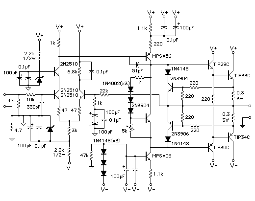
This simple audio power amplifier was originally designed for a circuit board workshop conducted by the OSU IEEE Student Group. At the workshop, 20 participants each constructed this amplifier by etching and drilling the single-sided circuit board, soldering all...
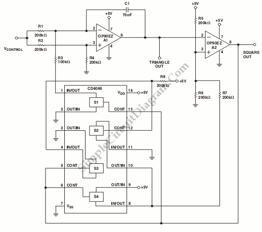
This is a schematic diagram of a micropower voltage-controlled oscillator circuit. This circuit can generate square and triangle wave outputs and only requires minimal power. The micropower voltage-controlled oscillator (VCO) circuit is designed to produce both square and triangle waveforms,...
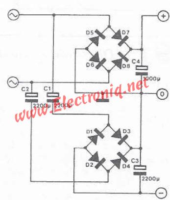
If a double power supply is desired but a center-tapped transformer is unavailable, an electronic circuit can be utilized in the following configuration. This circuit employs a second rectifier bridge connected to the secondary coil of the transformer, utilizing...
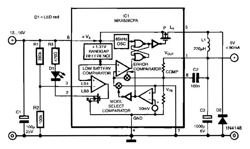
The circuit is straightforward due to the use of the MAX638CPA 5V CMOS Step Down Adjustable Switching Regulator IC. This IC converts an input voltage of 12 to 16 VDC into a stable 5VDC output. The circuit requires only...
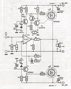
This simple MOSFET power audio amplifier circuit, featuring a TL071C operational amplifier and two MOSFET power amplifiers, can deliver up to 45W at an 8-ohm load. The schematic is based on Siliconix applications and incorporates variations in voltage across...
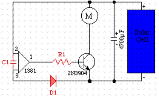
One 1381 part (CMOS voltage-controlled trigger available at different limits) should be selected to match the voltage across the motor (2V in this case). The other terminal of the motor is connected to a 3300µF capacitor, which is in...