
Transformerless Voltage Booster Circuit: A DC-DC Step-Up Switching Regulator Using Transistors

The DC-to-DC step-up converter operates on the principle of energy transfer through an inductor in a switching configuration. The circuit typically includes a power source, an inductor, a switching transistor, a diode, and a load. When the switching transistor is turned on, current flows through the inductor, storing energy in the magnetic field. Once the transistor is turned off, the inductor releases its stored energy, and the resulting voltage spike is directed to the output through the diode, effectively increasing the voltage.
The feedback mechanism involving the zener diode plays a crucial role in regulating the output voltage. The zener diode is connected to the output and provides a reference voltage. As the output voltage rises above the desired level, the zener conducts, providing feedback to the control circuit that adjusts the switching frequency of the transistors. This feedback loop ensures that the output voltage remains stable under varying load conditions.
The Schmitt trigger configuration formed by transistors Q1, Q2, and Q3 ensures a clean transition in the switching operation, minimizing voltage spikes and oscillations that could adversely affect performance. The choice of the 2N3053 transistor as the main switching element is due to its ability to handle higher currents, making it suitable for applications where load demands can vary significantly.
For practical implementation, the circuit layout should be optimized for minimal inductance and resistance in the connections to enhance efficiency. Proper heat dissipation techniques should also be employed, particularly for the 2N3053 transistor, to prevent thermal overload. Additionally, selecting the appropriate inductor and diode is critical for achieving the desired performance specifications, such as efficiency and output power capacity.
In summary, this step-up converter design is a robust solution for applications requiring a higher voltage from a lower voltage source, particularly in automotive and portable electronic devices. Its reliance on discrete components allows for customization and flexibility in design, making it an attractive option for engineers and hobbyists alike.A DC-to-DC step-up converter is traditionally implemented using transformer, working by converting the DC voltage to AC Voltage, step-up it using transformer, then rectify and filter the transformer`s output to get a higher DC voltage. Using a switching method, we can step-up a voltage without a transformer. We just need an inductor which is drive n by a switching transistor to boost the voltage. This circuit store the electric energy in an inductor before it is added to the input voltage, so this circuit is different than capacitor charge pump that store the electric energy using a capacitor. The most interesting this is that circuit use a discrete components: no integrated chip is required, only few transistors with few passive components.
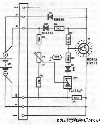
Because the switching topology is a boost converter, this circuit cannot be operated as step-down regulator, so the output will always be higher than the input. The voltage output is depend on the load because the feedback mechanism, through the zener diode, will maintain the output at about 14 volt, regardless the voltage input variation and load current variation.
The current from the voltage divider will flow through the zener diode if the output goes higher than the nominal value, and this condition will stop the oscillator built around the 2N3904 transistors. Stopping the oscillator will drop the output voltage and thus maintain the required voltage level at the output.
This transistors (Q1, Q2, and Q3) form a Schmidt trigger that drive the final transistor Q4 (the switching transistor 2N3053 ). This circuit is suitable for battery booster, if you need to run your 12 volt equipments on your old car that provide only a 6V supply from the battery.
The output of this voltage doubler can be adjusted by changing the voltage divider, or for easier adjustment, you can replace the 4, 7K resistor with a 5K potentiometer. Using a good inductor (low resistance), you can achieve up to 80% efficiency, and up to 2 Watt power can be delivered to the load.
For the main diode, you can use a 3 Ampere Schottky diode 1N5822. [Circuit`s schematic diagram source: Bill Bowden`s circuit collection] 🔗 External reference
Related Circuits
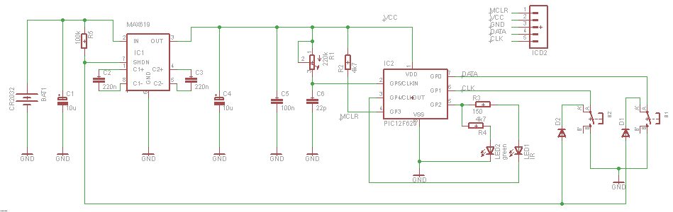
The Tiny Remote is a compact infrared remote control featuring only two buttons designed to operate an iRobot Roomba. It emits three different infrared signals. The Tiny Remote is designed for simplicity and ease of use, making it an ideal...
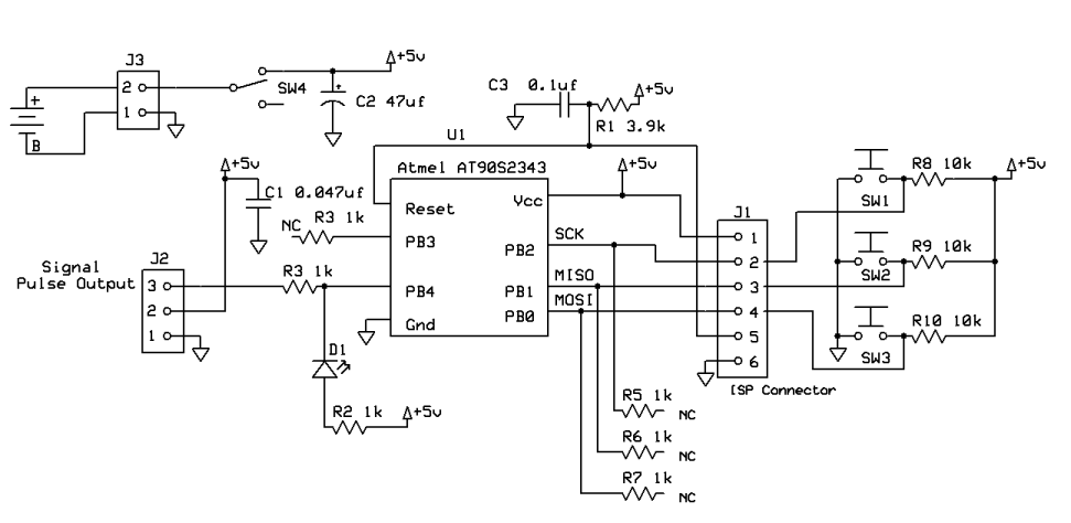
A PING Ultrasonic Range Finder is designed to create a system capable of detecting and measuring the distance (in millimeters) to the nearest object in front of the sensor. It functions similarly to a digital measuring tape; the user...
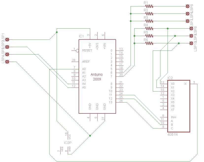
This guide explains how to set up an automated gardening system using an Arduino and other inexpensive electronic components. The system promotes sustainable gardening by utilizing sensors to measure soil moisture and a web scraper to forecast future weather...
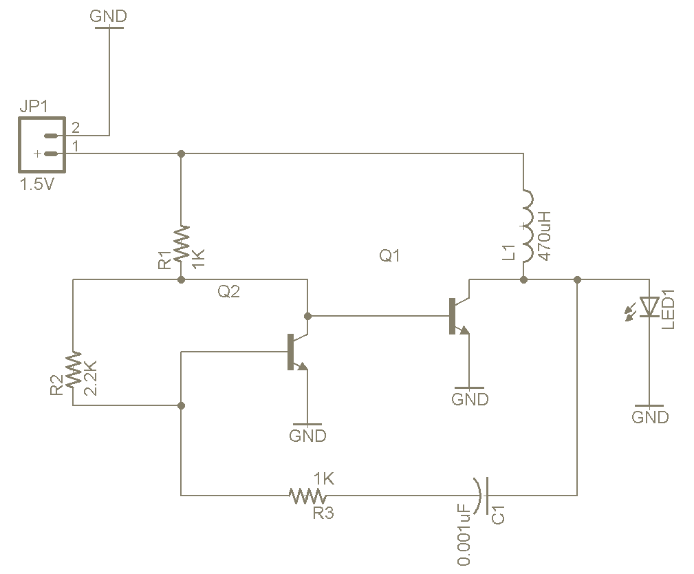
The Joule Thief is a straightforward and uncomplicated device, yet its functionality is remarkable. It can utilize a battery that is otherwise deemed unusable in any other electronic device, and it is very easy to construct on a breadboard...
This voltage regulator for devices that utilize solar cells is straightforward and requires only a few electronic components. When a rechargeable energy storage device is employed, the voltage regulator circuit facilitates charging when the output voltage of the cell...
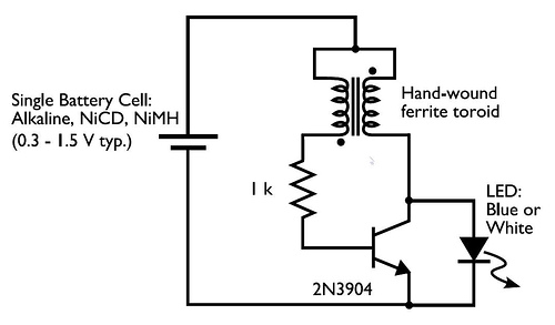
A transformer with two input leads and three output leads was used. An LED was connected to two of the output leads, and when a dead AA battery was connected to the input leads, the LED blinked for a...