
Transistor Checker Circuit

The circuit utilizes a 741 operational amplifier, which is a widely used component in analog electronics due to its versatility and reliability. The op amp is configured as a voltage follower, meaning that the output voltage directly follows the input voltage, resulting in no amplification but providing high input impedance and low output impedance. This characteristic is particularly useful in applications where signal buffering is required.
The use of a 50-meter movement indicates that the circuit is intended for applications requiring a visual representation of voltage levels, such as in analog voltmeters. The potentiometer R7 allows for fine-tuning of the zero point on the meter, ensuring accurate readings across the entire scale. Potentiometer R6 is critical for setting the full-scale reading, allowing the user to calibrate the meter to the desired maximum voltage range.
Calibration procedures are essential for ensuring the accuracy of the voltmeter. The initial step of setting R6 to the mid-position with no input helps establish a baseline for the meter's operation. Adjusting R7 to zero the meter ensures that the device can accurately measure voltages around the zero point, which is crucial for applications involving both positive and negative voltages. By applying a known voltage of 1 Vdc and adjusting R6 accordingly, the user can ensure that the meter provides accurate full-scale readings, thereby enhancing the reliability of the measurements taken.
The ability to adjust the voltmeter to read both positive and negative voltages expands its functionality, making it suitable for a wider range of applications. This dual capability is achieved through careful adjustment of R7, which centers the scale and allows for accurate readings regardless of the polarity of the input voltage. Overall, the described circuit is an effective and efficient solution for voltage measurement tasks in various electronic applications. The circuit is built around a 741 general-purpose op amp that is configured as a voltage follower; with the components shown, the op amp has a voltage gain of one. The output of the 741 is used to drive a 50- meter movement. Potentiometer R7 is used to zero the meter and R6 sets the meter`s full-scale reading, Calibrating the meter is a snap.
With no input applied to the circuit, set R6 to mid-position and adjust R7 to zero the meter. Once that is done, apply a positive 1-Vdc voltage to the input and adjust R6 for a full-scale reading. The voltmeter can be adjusted to read both positive and negative voltages by adjusting R7 for a center scale reading at the meter`s zero position and a positive 1- V reading at the meter`s full-scale position.
Related Circuits
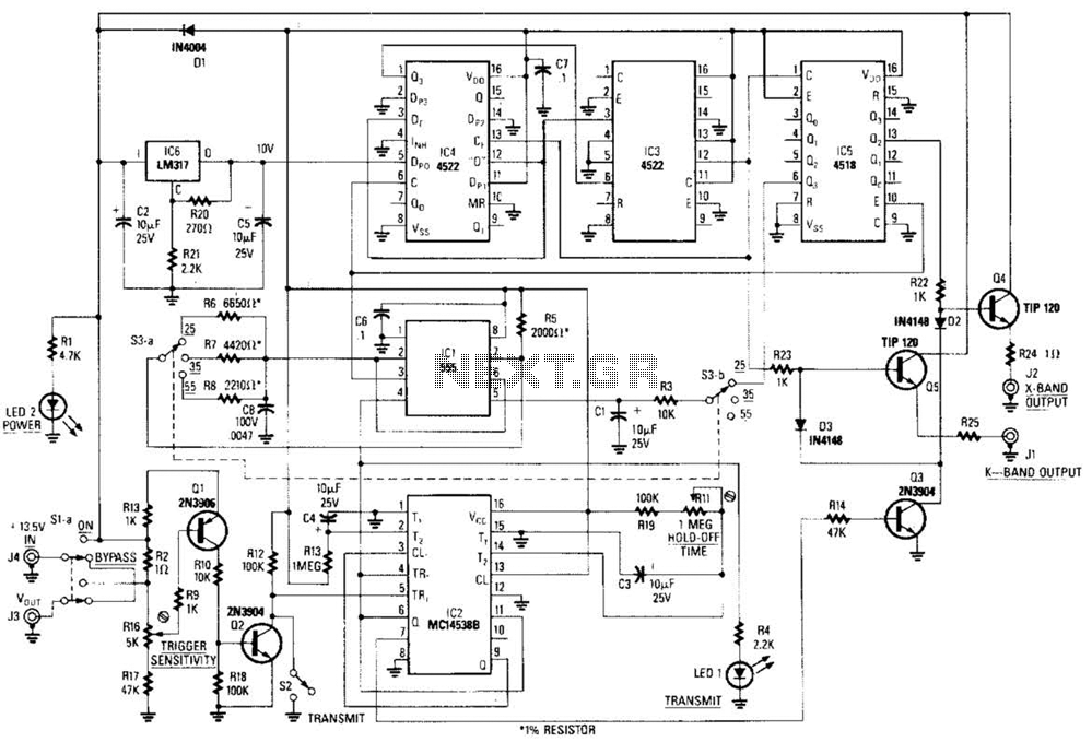
This circuit is a system designed to generate a pulsed modulation signal for a Gunn diode microwave oscillator. It features several preset speed settings (S3 a and b). A 555 timer is employed in conjunction with a frequency divider...
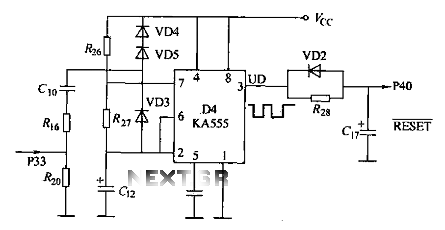
Anti-jamming circuit (watchdog circuit): KA555 interference when analog baseband circuit is shown in Figure 18-14. The KA555 is a hybrid analog/digital integrated circuit. The input signal is connected to specific pins, while the power supply is 5V and the...

The 10A H-Bridge Motor Controller circuit appears straightforward, but several critical aspects should not be overlooked. The primary components utilized in the circuit include the TIP147, TIP142, and 2N2222 transistors. The power supply circuit operates at +12V, which is...
Automatic color holiday lights circuit The automatic color holiday lights circuit is designed to control the operation of decorative lights during festive seasons. This circuit typically utilizes a microcontroller or a timer to manage the sequencing and color changes...
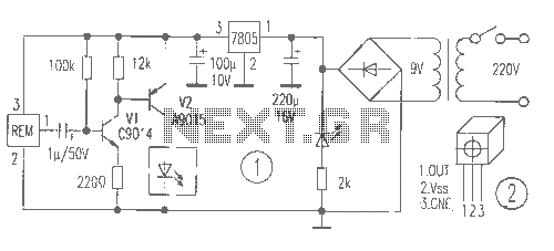
The receiver provides two TV signals, one for the living room and another for the bedroom, along with a satellite receiver. Watching television in the bedroom is convenient in Taiwan; however, when watching television in the living room, it...
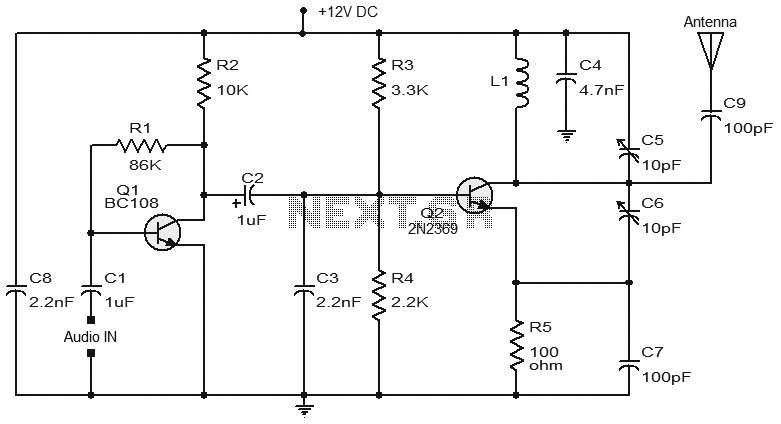
Numerous FM transmitter circuits have been published, and this is another example of a simple two-transistor FM transmitter. The first stage of the circuit is a preamplifier based on transistor Q1. This stage operates as a collector-to-base biased amplifier,...