
Radar Calibrator Circuit

The circuit utilizes a 555 timer in astable mode to generate a continuous square wave signal. This signal is then fed into a frequency divider chain, which is composed of flip-flops that divide the frequency of the input signal by a predetermined factor. The output of this chain produces various frequency outputs corresponding to the desired Doppler shift values.
The Gunn diode, which operates at microwave frequencies, is modulated by the pulsed signal generated from the 555 timer. The modulation of the Gunn diode allows for the generation of microwave signals that can be utilized in radar systems. The Doppler effect is crucial for measuring the speed of objects, and the circuit is designed to provide specific modulation frequencies that correspond to the desired speed settings.
The preset speed settings (S3 a and b) are implemented using a switch mechanism, allowing users to select between different operational modes easily. This flexibility is essential for applications requiring accurate speed measurements in radar technology.
Overall, this circuit design is integral for enhancing the performance of radar systems by providing modulated microwave signals that can adapt to various operational requirements in both X-band and D-band radar applications. The combination of the 555 timer and the frequency divider chain ensures precise control over the output frequencies, facilitating reliable Doppler shift measurements. This circuit is basically a system that generates a pulsed modulation signal for a Gunn diode microwave oscillator. Several speed settings are preset (S3 a and b). A 555 timer is used with a frequency divider chain to produce Doppler shift equivalents of 25, 35, and 55 rnph,
for both X- and D-band radars.
Related Circuits

Electronic FM Telephone Transmitter Schematic. The following schematic design illustrates a circuit diagram for an FM telephone transmitter built on a compact PC board layout. This small design allows it to be easily integrated within the housing of a...

This project presents numerous practical applications in security and alarm systems for homes, shops, and vehicles. The circuit is highly sensitive and can be configured to either reset automatically or remain triggered until manually reset after an alarm. It...
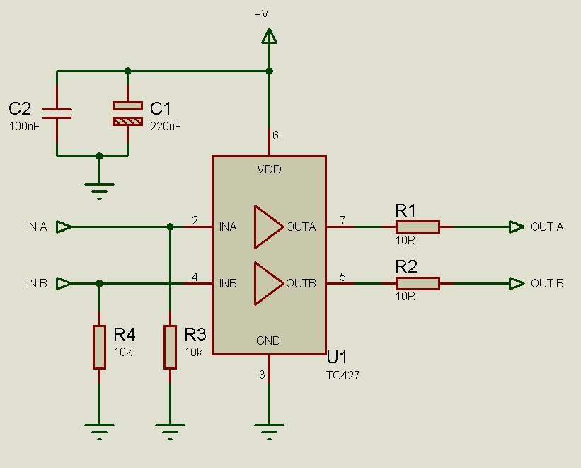
MOSFETs cannot simply be connected to the drive signal and expected to function correctly. Due to their construction, driving MOSFETs can be complex, particularly for beginners. Many users frequently seek assistance with MOSFET drive issues on various blogs, websites,...
The circuit consists of two differential amplifier transistors configured with a voltage dividing type bias circuit, measuring the resistance of four arms in a bridge configuration. The product includes a platinum resistance sensor, which exhibits an increase in resistance...
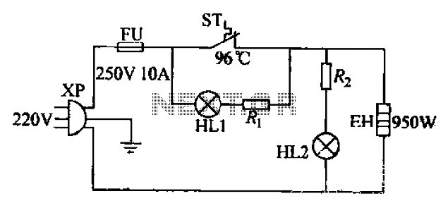
The 220V electric vibrator features a clip for insertion, with FU representing the fuse. ST indicates an inverter-like device, while HL1 and HL2 serve as indicators for insulation and heating. The EH component functions as the heater. When the...

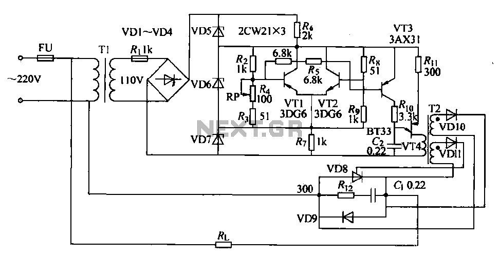
This is a design circuit for a soft light dimmer. The circuit utilizes the IGBT STGP10N50A and the TS555 timer as the main components. The timer is triggered by the zero crossing voltage pulse. The time constant, determined by...