
Transistor phase shift oscillator. RC phase shift network and RC phase shift oscillator using opap

The transistor RC phase shift oscillator is a type of electronic oscillator that generates sine wave signals. This oscillator utilizes a combination of resistors and capacitors to create a phase shift of 180 degrees, which is essential for the oscillation process. The circuit typically employs an operational amplifier (op-amp) to achieve the necessary gain and to facilitate the feedback required for sustained oscillation.
The RC phase shift network consists of multiple stages, typically three or more, of resistor-capacitor (RC) combinations. Each stage contributes a phase shift of approximately 60 degrees, resulting in a total phase shift of 180 degrees when combined. This is crucial for the feedback loop in the oscillator, as it allows the output of the op-amp to be fed back into its inverting input, establishing the conditions for oscillation.
The working principle of the RC phase shift oscillator is based on the concept of positive and negative feedback. The op-amp amplifies the signal, and the RC network introduces the necessary phase shift. The frequency of oscillation is determined by the values of the resistors and capacitors used in the circuit. The formula for calculating the frequency of oscillation (f) in a three-stage RC phase shift oscillator can be approximated as:
f = 1 / (2πRC√6)
Where R is the resistance and C is the capacitance of the components in the RC network. The circuit diagram typically illustrates the arrangement of the op-amp, resistors, capacitors, and the feedback loop, providing a clear visual representation of the oscillator's configuration.
In practical applications, this type of oscillator is used in various audio and signal processing circuits, where a stable sine wave output is required. The simplicity and effectiveness of the RC phase shift oscillator make it a popular choice in electronic design.Transistor RC phase shift oscillator . RC phase shift oscillator using opamp. RC phase shift network. Theory and working principle. circuit diagram.. 🔗 External reference
Related Circuits

Assume the correct phase sequence to be VA-VB-VC. The circuit terminals are connected such that T1 gets connected to phase A and T2 to phase B. The capacitor advances the voltage developed across R2 due to phase B by...
The 27MHz quartz crystal oscillator circuit is illustrated in figure 1. The biasing circuit consists of resistors R1, R2, and R3, while C6 serves as the bypass capacitor. The partial voltage circuit includes capacitors C1, C2, C3, and C4...
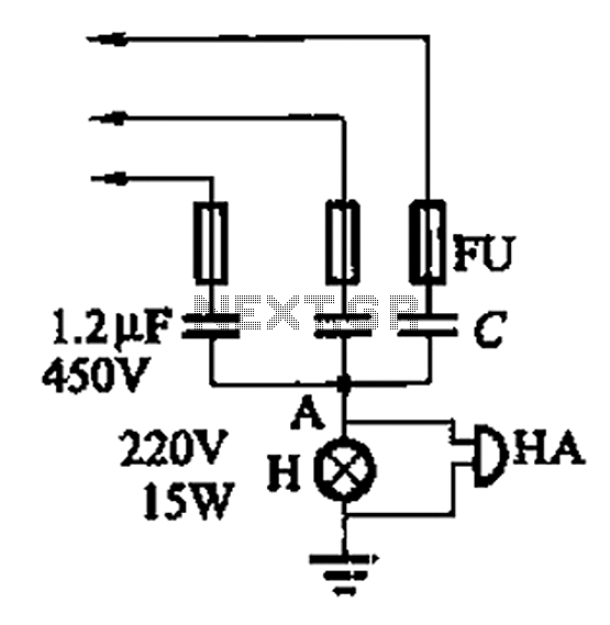
A 3-phase power system poses risks to electrical equipment, particularly asynchronous motors. To detect phase failure, an alarm circuit can be implemented. When the power supply is normal, the voltage at point A is approximately 0V, and no alarm...
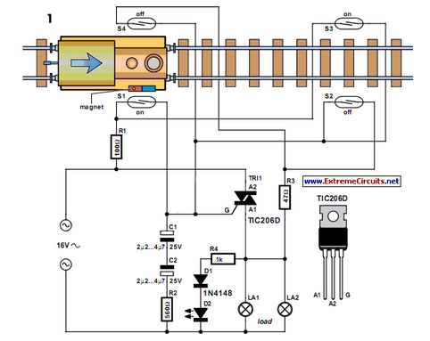
Modern electronics is essential for every large model railroad system, providing solutions to nearly every issue. Although ready-made products are available... Modern model railroad systems rely heavily on advanced electronics to enhance functionality and user experience. These systems often incorporate...
The circuit demonstrates the application of the ZN414 integrated circuit (IC) to create a compact AM radio receiver. The ZN414 IC is a combination of a transistor and a tuned radio frequency (TRF) circuit. The ZN414 IC is specifically designed...
This module utilizes the highly integrated MAX2830 RF transceiver, providing a complete RF front-end solution that complies with the WLAN IEEE 802.11b/g standard. The MAX2830 RF transceiver is designed for wireless communication applications, specifically targeting WLAN systems. It integrates various...