
transistor tester circuit

The transistor tester circuit is designed for ease of use and accuracy in evaluating the functionality of bipolar junction transistors (BJTs). The circuit operates with a 6V power supply derived from a 230V AC input through a step-down transformer, ensuring safety and compatibility with standard household voltage levels. The rotary switch S1 is integral to the circuit, allowing the user to select from multiple base resistors, which is essential for accommodating various transistor specifications and ensuring accurate testing.
The arrangement of the transistor leads is critical; incorrect connections can lead to erroneous readings or potential damage to the transistors. The emitter, base, and collector are distinctly marked on the circuit board, providing clear guidance for proper connections. When an NPN transistor is correctly connected and functioning, the green LED illuminates, providing immediate visual feedback. Conversely, when a PNP transistor is tested and found to be operational, the red LED lights up, indicating successful testing.
This circuit is particularly useful for hobbyists and engineers who require a straightforward method to verify the operational status of transistors. Its simplicity and effectiveness make it a valuable tool in both educational and practical electronics applications.This is a very simple transistor tester circuit the circuit can be used to test NPN and PNP transistors. The voltage source is a 6V power supply which is 230V AC to 6V step down transformer. It is essential to put the transistor leads in right direction like transistor emitter to circuit emitter where (E) is marked transistor base to circuit base
marked (B) and transistor collector to circuit collector marked (C). The switch S1 is a rotary switch to choose a correct base resistor for under test transistor. The green LED will glow when an under test NPN transistor is working correctly and red LED will glow when an under test PNP transistor is working correctly. 🔗 External reference
Related Circuits
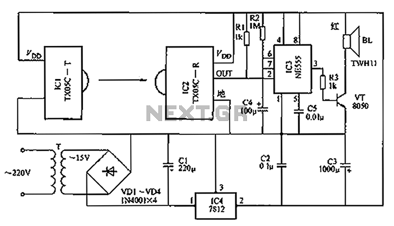
A new type of infrared system utilizes the TX05C radio sensor module for a burglar alarm designed for doors and windows. This system operates in the infrared spectrum, which is invisible to the human eye, making it suitable for...
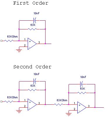
The circuit design involves a circular operational amplifier (op-amp) configuration that functions as a second-order low-pass and high-pass filter. The low-pass filter operates within a frequency range of 20 to 250 Hz, while details regarding the high-pass filter are...
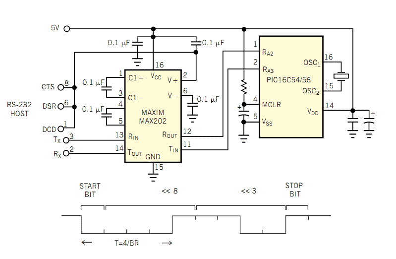
The popularity and easy access of RS-232 ports lend them to many communication projects. You can use a port as is or as a tiny parallel port when the exchange uses only control lines. Before the asynchronous serial-data transfer...
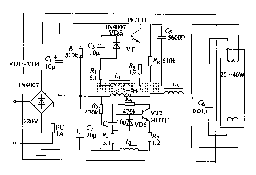
Electronic ballasts operate over a wide voltage range, provide fast startup with no noise or flicker, and contribute to energy savings. Their acceptance among users has been increasing. The circuit depicted in the figure represents a typical electronic ballast...
Do you have disco ears? If people ask you this and you are still well below 80, you may be experiencing hearing loss, which can result from prolonged exposure to loud music. The severity of the issue may not...
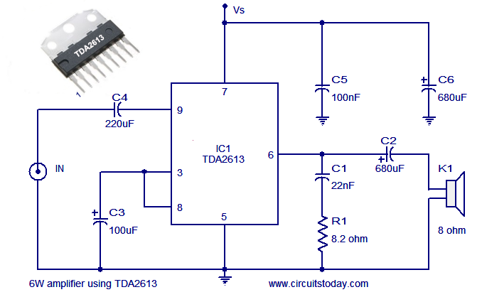
A simple and easy-to-build Hi-Fi audio power amplifier circuit is presented here. This 6-watt Hi-Fi audio amplifier circuit utilizes the TDA2613 integrated circuit (IC). The circuit design employs the TDA2613, which is a high-performance audio amplifier IC known for its efficiency...