
Audio power amplifier circuit using Hi Fi audio amplifier IC TDA2613

The circuit design employs the TDA2613, which is a high-performance audio amplifier IC known for its efficiency and sound quality. It is capable of delivering up to 6 watts of output power, making it suitable for driving small speakers in various audio applications. The TDA2613 features built-in thermal protection and short-circuit protection, enhancing the reliability of the amplifier.
The basic configuration of the circuit includes the TDA2613 connected to a power supply, typically ranging from 12V to 18V, depending on the desired output power and speaker impedance. Input audio signals are fed into the amplifier through capacitors that block any DC offset, ensuring only the AC audio signal is amplified. The output stage of the amplifier is designed to drive a load, such as an 8-ohm speaker, providing clear and dynamic sound reproduction.
Additional components in the circuit may include resistors for gain adjustment, capacitors for filtering and stability, and a heat sink attached to the TDA2613 to dissipate heat generated during operation. Proper layout and grounding techniques are essential to minimize noise and ensure optimal performance of the amplifier.
This Hi-Fi audio amplifier circuit is ideal for hobbyists and audio enthusiasts looking to build a compact and efficient amplifier for personal audio projects.A simple and easy to build Hi Fi audio power amplifier circuit is shown here. This 6 watt hi Fi audio amplifier circuit uses TDA2613 IC.. 🔗 External reference
Related Circuits
Electronic schematics collections provide a platform for discussions related to electronic circuit schematics, printed circuit board (PCB) diagrams, and various electronics projects. These collections serve as valuable resources for engineers, students, and hobbyists interested in electronics design and development. They...
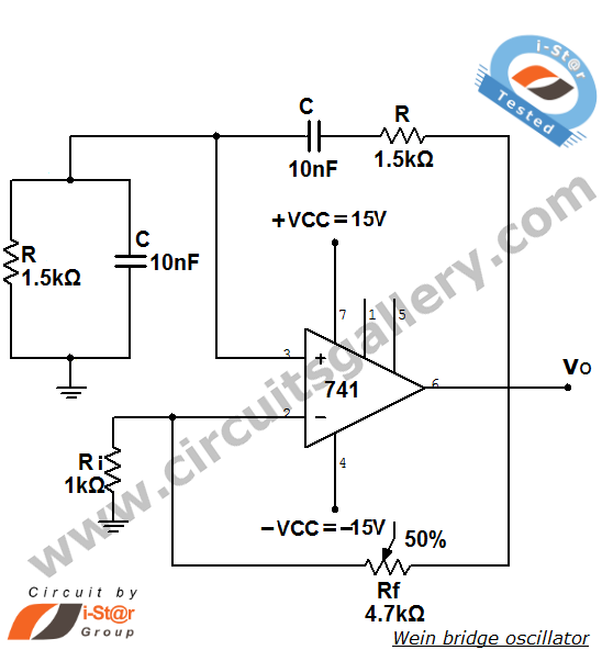
The Wien bridge oscillator is a high-stability audio frequency sine wave oscillator known for its simplicity. An oscillator is defined as a circuit that generates periodic electric signals, such as sine waves or square waves. Applications of oscillators include...
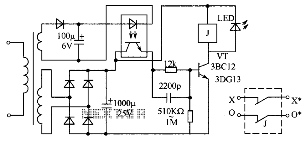
The circuit protection mechanism utilizes optocouplers for on-off control. Under normal voltage conditions, the output from the optocouplers is minimal, and the VT transistor operates in reverse bias. However, if the circuit voltage increases due to reasons such as...
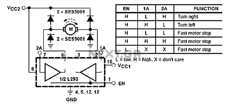
All inputs are compatible with TTL. Each output consists of a complete totem pole driver circuit, utilizing Darlington transistors and pseudo-Darlington sources. The driver enable signals, labeled as 1,2 EN and 3,4 EN, control the activation of drivers 1...
The Colpitts oscillator has been redrawn for clarity. The inductor (L) is approximately 1.5 µH with 19 turns wound on a T50-6 core (yellow). The capacitor (C6) value has been determined experimentally, with a combination of 69 pF (using...
The circuit operates by using a clock signal to drive four D-flip-flops in the control section, which store the on/off state of each current direction for the two stepper motor coils. The flip-flops create a finite state machine (FSM)...