
Transistorized Bar-Graph Driver

The circuit comprises a series of resistors (R1 to R10) forming a network that serves as a voltage divider, providing appropriate biasing levels for the transistor emitters. The emitter followers (Q1 and Q2), typically configured as bipolar junction transistors (BJTs), are used to buffer the voltage from the resistor network. This configuration allows for high input impedance and low output impedance, ensuring minimal loading on the preceding stage while effectively driving the LED drivers (Q3 through Q7).
The LED drivers are responsible for illuminating the LEDs in accordance with the audio signal levels. As the audio signal amplitude varies, the voltage across the resistor network changes, which in turn modulates the base voltage of the emitter followers. The output from the emitters of Q1 and Q2 is then fed into the bases of Q3 through Q7, which are configured to drive the LEDs. This arrangement allows the circuit to produce a visual representation of the audio signal's volume, effectively creating a "light organ" effect.
The circuit can be connected to various audio sources, including speakers or direct audio outputs from devices, making it versatile for different applications. The design ensures that the LEDs illuminate in a manner proportional to the audio input, providing an intuitive visual feedback mechanism for users. The use of multiple LED drivers allows for a more dynamic and visually appealing display, as different LEDs can light up at varying intensities based on the audio signal's characteristics. A resistor network (Rl through RIO) with emitter followers (Ql and Q2) drives LED drivers (Q3 through Q7). This circuit was used as a "light organ" to provide visual volume indication. It can be hooked to a speaker, to another audio source, etc.
Related Circuits
More: A comprehensive electronic schematic involves the representation of electrical components and their interconnections in a circuit. Each component is typically represented by standardized symbols, and the connections between them are depicted using lines. The schematic provides essential information...
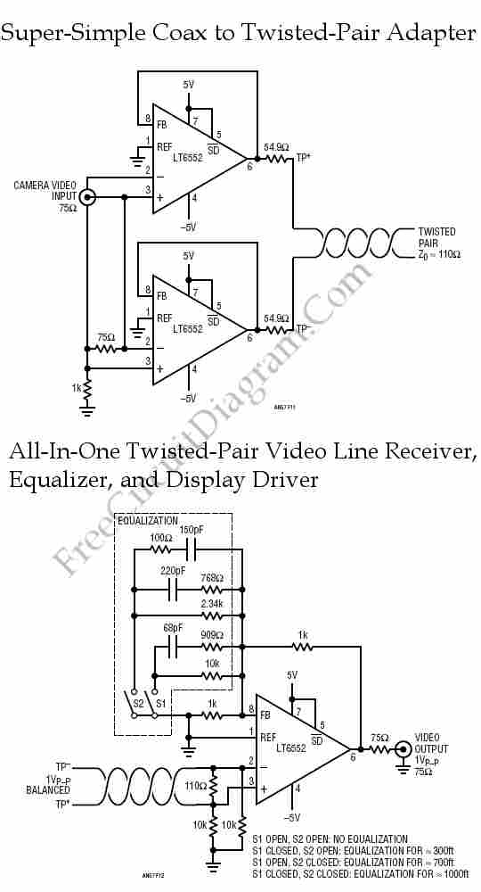
Twisted-pair wiring is a wiring technique commonly utilized for in-building data communication. Compared to conventional coaxial cable, this technique offers various advantages. Twisted-pair wiring consists of pairs of insulated copper wires that are twisted together to form a single cable. This...

The drive circuits for unipolar stepper motors are typically straightforward. In their simplest configuration, a transistor or MOSFET is employed to control each section of the windings. The control signal must be supplied programmatically to the four windings of...

This circuit utilizes a wideband, high slew rate CA3100 BiMOS operational amplifier. The slew rate for this amplifier is 28 V/µs. The output swing is 9 volts peak-to-peak into a terminated line, measured at the termination. The CA3100 BiMOS operational...

A schematic of a typical transistor AM radio is presented. This circuit utilizes npn transistors. It is a generic circuit; hence, specific values for some components are not provided. This circuit serves as a reference point for experimenters. The schematic...

The circuit utilizes a 100-ohm isolation resistor that allows the amplifier to drive capacitive loads greater than 500 pF. This resistor effectively isolates high-frequency feedback from the load, contributing to circuit stability. Low-frequency feedback is returned to the amplifier's...