
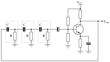
transistors Low power low voltage slow (0.1Hz) oscillator
 oscillator")
The circuit described is a low-power SCR triggering system designed to operate efficiently within a specified voltage range. The primary function of this circuit is to periodically trigger an SCR, which allows for controlled switching in various applications, such as in lighting or motor control systems.
The circuit operates by utilizing a timing mechanism that generates a pulse every 10 to 30 seconds, depending on the power supply voltage. A resistor-capacitor (RC) timing network can be employed to achieve the desired timing intervals. The capacitor is charged through a resistor, and once it reaches a threshold voltage, it can trigger the SCR. The design must ensure that the capacitor charging current does not exceed 10 µA, which necessitates careful selection of resistor values to extend the timing intervals at lower voltages.
In terms of voltage operation, the circuit is designed to function effectively at a minimum of 1.8 VDC and up to 7.0 VDC. This range allows for flexibility in power supply choices, accommodating both battery-operated and mains-powered applications. The design should incorporate components that can reliably operate within this voltage range without significant power loss.
Cost-effectiveness is a critical factor in the design process. The use of low-cost components such as resistors, capacitors, and the SCR itself is preferred over more expensive alternatives like microcontrollers. This approach not only reduces the overall cost of the circuit but also simplifies the design, making it easier to implement in various applications.
Overall, the circuit must be optimized for low power consumption, reliable operation across a specified voltage range, and cost efficiency, ensuring that it meets the requirements while remaining practical for real-world applications.The power supply varies, and the circuit must operate on under 10uA of current (not counting charging the cap). It triggers an SCR every 10-30 seconds as long as the power supply is above 1. 8VDC, and must operate across a range of 1. 8 and 7. 0 VDC. The timing isn`t critical - around 10-30 second intervals to trigger the SCR is fine (a short positiv
e pulse). The lower the voltage, the longer the time interval is fine. The kicker is the low current requirement (10uA or less), low voltage requirement (1. 8V) and, as always, low cost (ie, replacing a 10 cent PUT with a 30 cent microcontroller would not be ideal). 🔗 External reference
Related Circuits
For successful circuit-building exercises, follow these steps: Measure and record all component values before constructing the circuit, selecting resistor values that are sufficiently high to minimize the risk of damaging any active components. In case of significant errors (greater...
A dimmer switch is an electrical device that can replace standard switches used for lamps, heaters, or certain types of electric motors. Dimmer switches allow for the adjustment of light intensity and power levels. Dimmer switches operate by varying the...
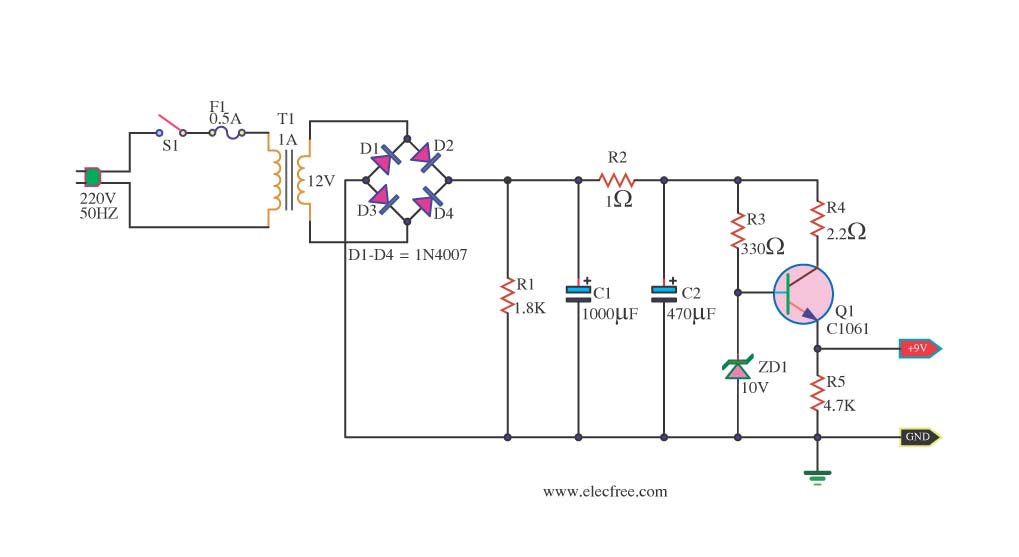
This is a DC power supply circuit designed to regulate 9 volts and provide a current output ranging from 1 amp to 2 amps. The circuit utilizes a modified TIP31 transistor, although alternative transistors such as TIP41, MJE3055, or...
A friend is interested in building a hi-fi power amplifier, specifically a Class AB model due to its quality sound, particularly in bass response and distinct clarity. This circuit is designed as a hi-fi OCL (Output Capacitor-Less) power amplifier...
This circuit is an enhanced Hartley oscillator, which allows for frequency adjustment within a specified range by altering the base current. The output signal amplitude exceeds 6V when tested with a 6kΩ load resistance, making it suitable for use...
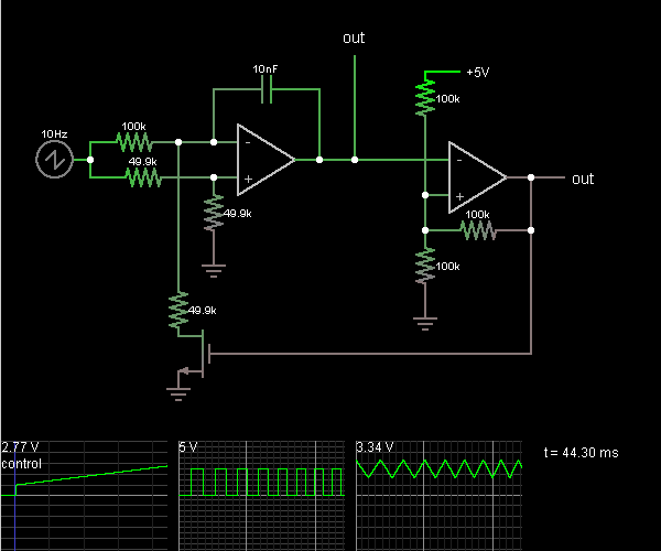
This circuit is a voltage-controlled oscillator, which is an oscillator whose frequency is determined by a control voltage. A 10 Hz sawtooth oscillator provides the control voltage in this case; this causes the frequency to rise slowly until it...