
Transmitter Detector for FM Bug Surveillance

The circuit design utilizes a 9 V battery as the primary power source, making it suitable for portable applications. The core function of this circuit is to detect the presence of bugs, which typically operate within specific frequency ranges. The use of frequency modulation (FM) allows for the transmission of audio signals over varying frequencies, which can be intercepted by the circuit.
Key components likely include an antenna for signal reception, a radio frequency (RF) amplifier to boost the received signals, and a demodulator to convert the modulated signal back into its original form. The antenna captures the frequency-modulated signals emitted by the bugs, while the RF amplifier enhances the weak signals for better processing.
The demodulator, which may be implemented using a simple integrated circuit or discrete components, extracts the audio information from the frequency-modulated carrier wave. This information can then be analyzed or monitored through an output stage, which could consist of an audio amplifier connected to a speaker or a recording device.
Additional filtering components may be included to eliminate unwanted noise and improve the clarity of the detected signals. Capacitors and resistors can be used to create low-pass or band-pass filters, allowing only the desired frequency range to pass through while attenuating other frequencies.
Overall, this circuit serves as a practical solution for detecting and monitoring the activities of bugs operating within specific frequency ranges, providing valuable insights into their transmission behavior.The circuit was constructed using a few components that is powered by a 9 V battery for sensing the presence of bugs transmitting within the frequency mod. 🔗 External reference
Related Circuits

The core of any transmitter is typically an oscillator circuit, and in simple transmitters, such as QRSS devices, a crystal is often used. Frequency adjustment is achieved by modifying the capacitance to ground on one of the crystal's legs....
This is a nice 2 Watts FM transmitter. It has a Super-Sensitive pre-amplification with BC109 and BC177 with more than 100% signal modulation. The job finish the 2N2219 by Motorola. For the Coils you should use 1mm wire(enameled), L1=...
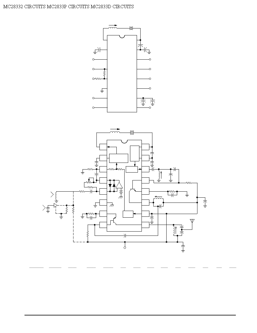
Crystal X1 operates in fundamental mode and is calibrated for parallel resonance with a load capacitance of 32 pF. The final output frequency is produced through frequency multiplication within the MC2833 integrated circuit (IC). The RF output buffer at...

The working principle of this inexpensive and simple-to-build metal detector circuit involves mixing two equal frequencies, which results in a low-frequency interference. The metal detector circuit operates on the principle of heterodyning, where two frequencies are combined to produce a...

All components used in the Moving Sensor/Detector Schematic Diagram utilize the IC NE555 and the Phototransistor L14F. The primary component in this circuit is the IC NE555, along with an IR LED, the Phototransistor L14F, and the IC LM1458....
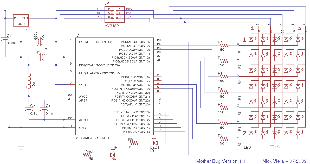
Mother Bug is a simple, interactive electronic message board disguised as a "bug." Text messages are pre-programmed into the memory of the device's microcontroller. When triggered, the microcontroller uses a 5 x 7 LED matrix display to show the...