
Cheap Metal Detector Circuit

The metal detector circuit operates on the principle of heterodyning, where two frequencies are combined to produce a new frequency. In this case, the circuit typically employs an oscillator to generate two signals of equal frequency. These signals are then mixed in a non-linear component, such as a diode, which creates beat frequencies as a result of the interference between the two signals. The output from this mixing process generates a low-frequency tone that is indicative of the presence of metal.
The circuit generally comprises several key components: an oscillator, a mixer, an amplifier, and a speaker or headphone output for audio feedback. The oscillator can be implemented using a simple LC circuit or a dedicated oscillator IC, providing a stable frequency output. The mixer can be realized with a diode or a transistor configured in a way to facilitate the mixing of the two frequencies.
When metal is introduced into the detection field, it alters the electromagnetic field generated by the oscillator. This change modifies the frequency of the signals being mixed, resulting in a shift in the beat frequency. The amplifier then boosts this signal to a level that can be easily heard through the output device, alerting the user to the presence of metal.
The simplicity of the design allows for easy assembly and low-cost components, making it accessible for hobbyists and educational purposes. This circuit can serve as an excellent introduction to the principles of electronics, frequency mixing, and metal detection technology.The working principle of this cheap and easy to build metal detector circuit consists in mixing two equal frequencies which causes a low-frequency interfer.. 🔗 External reference
Related Circuits

This simple circuit can monitor the overflow of water from the overhead tank. The sensor placed close to the lid of the overhead tank continuously monitors the presence of water. The described circuit functions as a water overflow monitoring system...
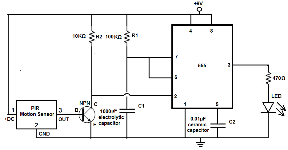
Many individuals install motion detectors in their backyards or homes to automatically turn on lights when movement is detected. Motion sensor lights have gained popularity and are increasingly utilized in various settings. Businesses frequently employ them in bathrooms, where...
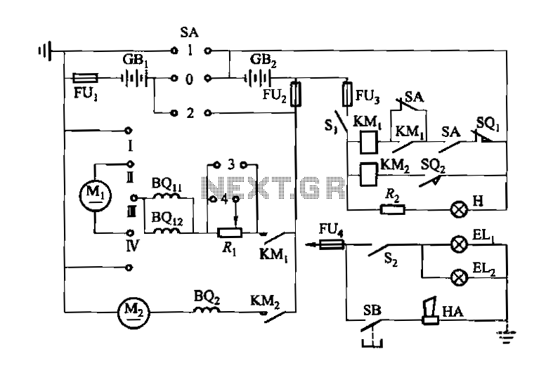
Denote cam controller SA 1 contact closure case. M1 is 1.35 kW driving motor, M2 is a 4 kW pump motor. The circuit involves a cam controller designated as SA 1, which is responsible for managing the operation of...
%2Band%2B(US)%2BCX500%2BC%2B1979-81%2Band%2B1979%2BCX500%2BD%2BElectrical%2BWiring%2BDiagram.jpg)
Lamp Electrical Circuit Diagram Manual PDF Download. This document provides a comprehensive manual for downloading the electrical circuit diagram of a lamp. The circuit diagram serves as a crucial reference for understanding the electrical connections and components involved in lamp...
The purpose of this circuit is to animate shop windows using a capacitive sensor positioned behind a postcard-like banner. The card is placed against the glass inside the shop window, allowing visitors to activate the relay by placing their...
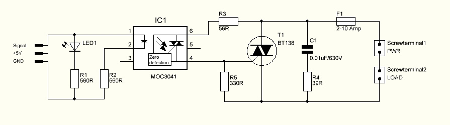
The triac is expected to activate and illuminate the light at nearly 100% brightness; however, it does not turn on at all. If the gate is continuously triggered (i.e., a constant voltage is applied to the gate), the light...