
Transmitting audio over laser or LED

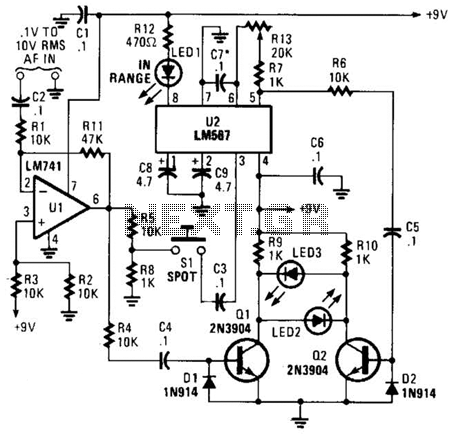
This circuit is designed to transmit audio signals wirelessly through light modulation, utilizing an LED as the transmitter and a cadmium sulfide (CdS) photocell as the receiver. The fundamental principle involves amplitude modulation, where the audio signal alters the intensity of the LED light output. As the LED's brightness changes in response to the audio signal, the CdS photocell detects these variations in light intensity, resulting in a corresponding change in its resistance.
The circuit configuration includes two audio transformers, each capable of handling impedances ranging from 8 to 1000 ohms. The transformer on the receiving side is particularly significant, as it serves as a voltage booster, enhancing the signal for better detection and processing. The integration of a battery and resistor in the receiving circuit is crucial for providing the necessary power and stability for the photocell operation.
It is important to note that the choice of an LED over a laser pointer was made to avoid potential damage, as initial experiments with a laser pointer resulted in failure. The audio input from a sound card, typically around 1 Volt AC at maximum output, is modulated and transmitted as light. On the receiving end, this signal is amplified, with measurements indicating that the output can reach approximately 12.5V, although variations may occur based on the specific components and configurations used.
In summary, this circuit represents an innovative approach to wireless audio transmission, leveraging light modulation techniques to achieve effective communication over short distances. Proper component selection and careful assembly are essential to ensure reliable performance and signal integrity.Want to send your audio information via a light wave across the room I built this simple circuit with some modifications that transmits an audio signal via light. The signal simply amplitude modulates the light intensity (aka AM) of a LED and a receiving cadmium sulfide photocell changes its resistance as the intensity varies.
Both sides have 8 t o 1000 ohm audio transformers, although on my circuit I ended up using the transformer on the receiving side as a voltage booster. I also added a battery and resistor to the photocell receiving side. Be careful-I used an LED because I destroyed a cheap laser pointer when trying the first circuit. The problem with it is the sound card audio is approximately 1 Volt AC at max, and this gets converted to ~12.
5V on the other side (although I found output was usually around. 5 V on the sound card and ~4 to 5V on the other side of the transformer). At least that`s what I measured-I`ve seen people read 4V on sound cards, but I don`t know which is correct. 🔗 External reference
Related Circuits
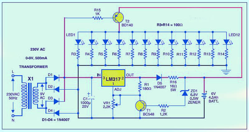
This is a low-cost circuit diagram for an emergency light utilizing a white LED. Components include an LM317 IC, a resistor, a transformer, an LED, and a variable resistor. The emergency light circuit using a white LED is designed for...
When the preset is set to its maximum, the LED flashes approximately every half second. This flashing rate can be increased by using a larger capacitor value, for instance, changing from 10µF to 22µF will result in a flashing...
The original description discusses a modular preamplifier that is simpler in construction yet exceptional in quality. The philosophy behind this circuit is that simplicity can also lead to better results. The circuit only uses a volume potentiometer. The Tape Monitor...
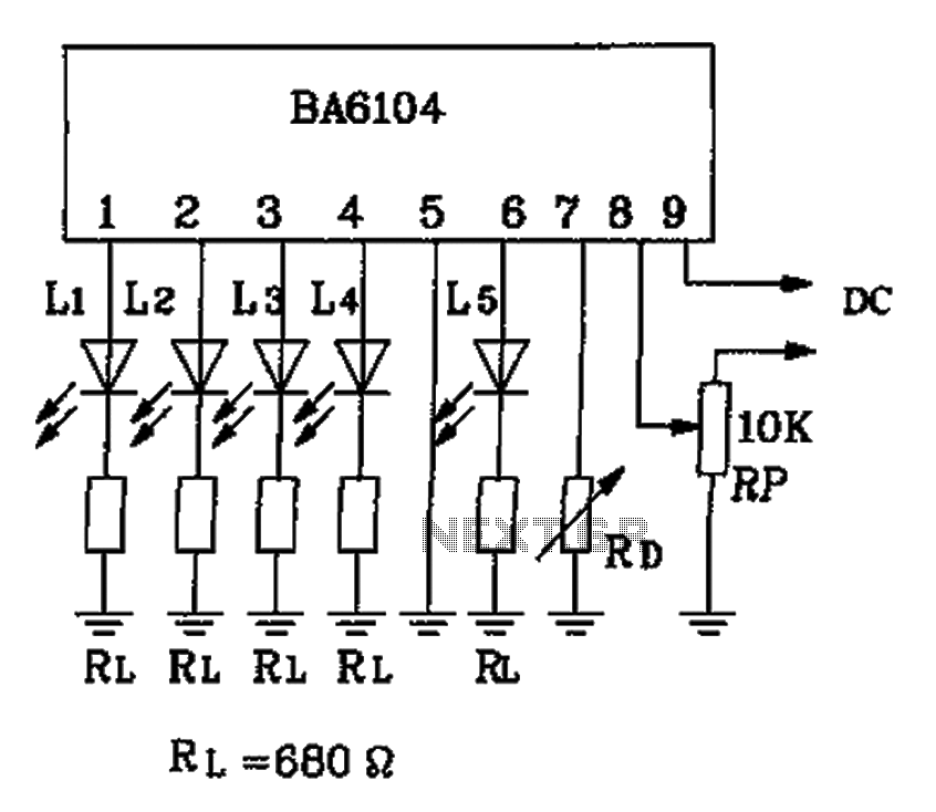
The BA6104 is a five-digit LED level meter driver integrated circuit (IC) used in basic application circuits. When the input level exceeds the required display threshold of 1V, only 7 feet of the power supply Vcc are indirectly affected...
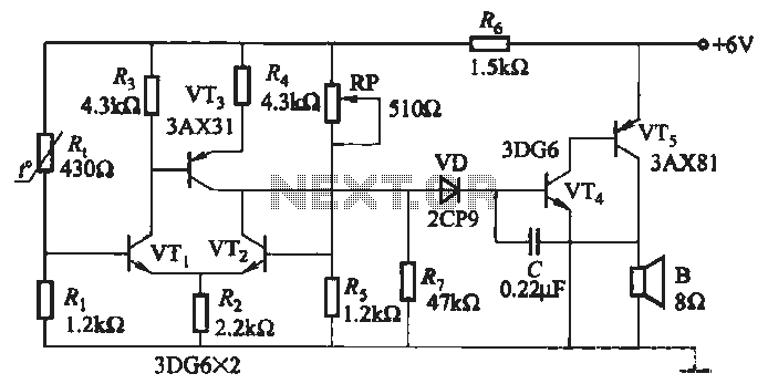
A negative temperature coefficient thermistor is utilized as the temperature sensing element (Rt). The circuit includes a resistor (Ri), a resistor (Rs), a potentiometer (RP), and the thermistor (R) to form a temperature bridge. A differential amplifier is created...
This meter is unique as it does not utilize a D'Arsonval movement or digital display for frequency readings. Instead, the measured frequency is indicated on a hand-calibrated dial. Any audio signal applied to the circuit is amplified by U1,...