
Triac motor drive circuit

The triac motor drive circuit is designed to control the operation of AC motors using a TRIAC as the primary switching element. A TRIAC is a semiconductor device that can conduct current in both directions when triggered, making it suitable for controlling AC loads. The circuit typically includes components such as resistors, capacitors, and diodes, which work together to manage the triggering and operation of the TRIAC.
In the configuration shown in figure (a), the main components are arranged to ensure that the TRIAC can be triggered at the appropriate phase angle of the AC waveform. This phase control allows for variable speed operation of the motor, as adjusting the triggering point alters the effective voltage and current supplied to the motor.
Figure (b) illustrates how the motor coils are connected to the circuit. The connections must be made carefully to ensure that the motor operates efficiently and safely. The design may also incorporate protective elements such as fuses or circuit breakers to prevent damage from overcurrent conditions.
The overall design of the triac motor drive circuit emphasizes reliability and efficiency in motor control applications, making it ideal for various industrial and consumer applications. Proper thermal management is also essential, as TRIACs can generate heat during operation, necessitating the use of heat sinks or other cooling methods to maintain optimal performance.Triac motor drive circuit b Shows the motor drive circuit TRIAC TRIAC has been called solid state relays. Figure (a) shows a circuit configuration diagram (b) shows the connection of the motor coils.
Related Circuits
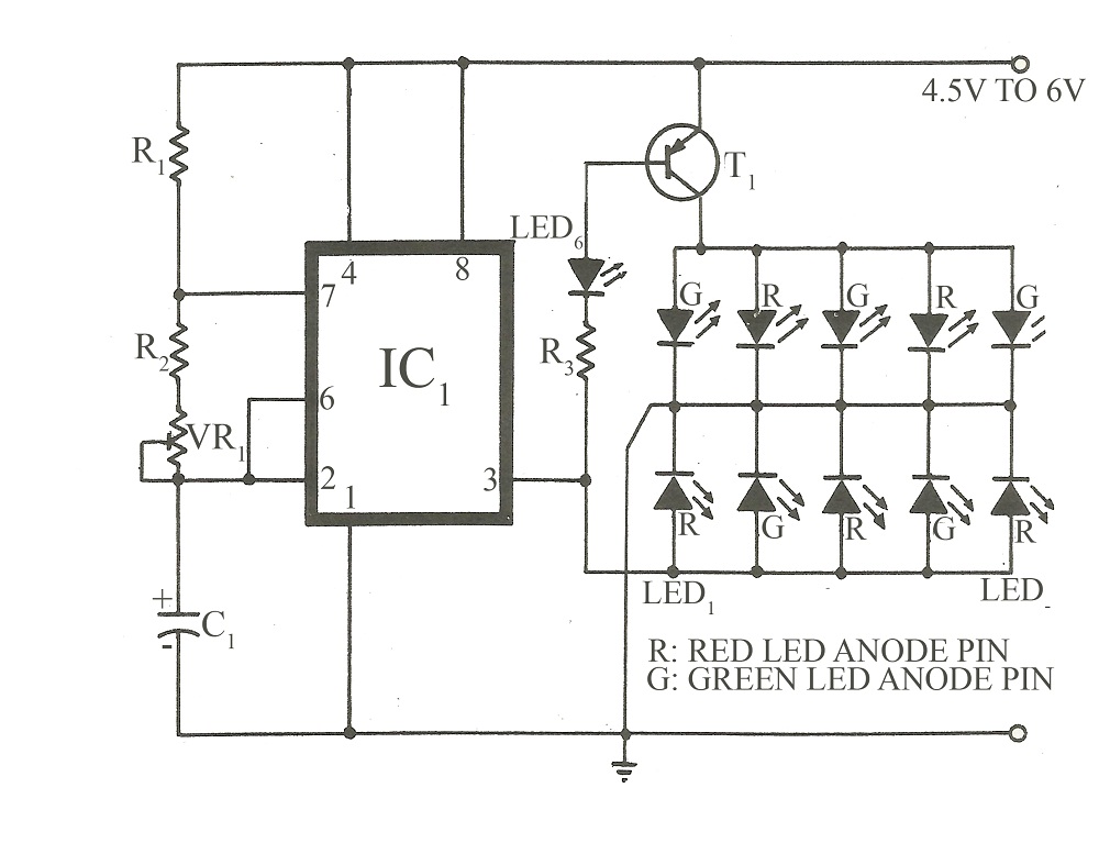
This circuit is similar to various published flasher circuits that utilize the IC 555 as a free-running multivibrator. The primary distinction is in the method of flashing bi-color LEDs. When the output at pin 3 of the IC 555...
This circuit differs from similar circuits in view of its simplicity and a totally different concept of generating the control signals. Usually remote control circuits make use of infrared light to transmit control signals. Their use is thus limited...
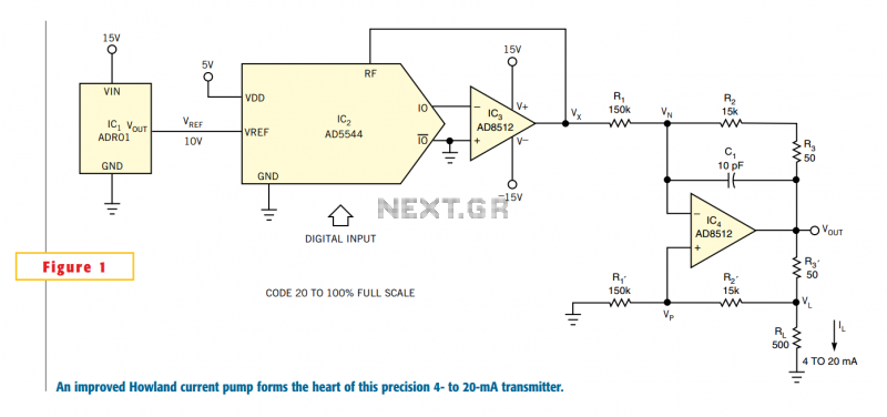
One of the key challenges in the design of 4- to 20-mA current transmitters is the voltage-to-current conversion stage. Conventional transmitters use multiple op amps and transistors to perform the conversion function. These approaches have been around for a...
An RF power amplifier is a type of electronic amplifier used to convert a low-power radio-frequency signal into a larger signal of significant power, typically for driving the antenna of a transmitter. It is optimized for high efficiency, high...
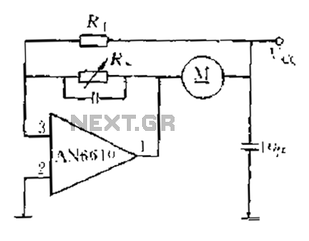
AN6610 Application Circuit operates as follows: When the supply voltage (Vcc) changes due to mechanical load variations, it can affect the motor speed. The motor speed is proportional to the back electromotive force (EMF). Consequently, the voltage across the...
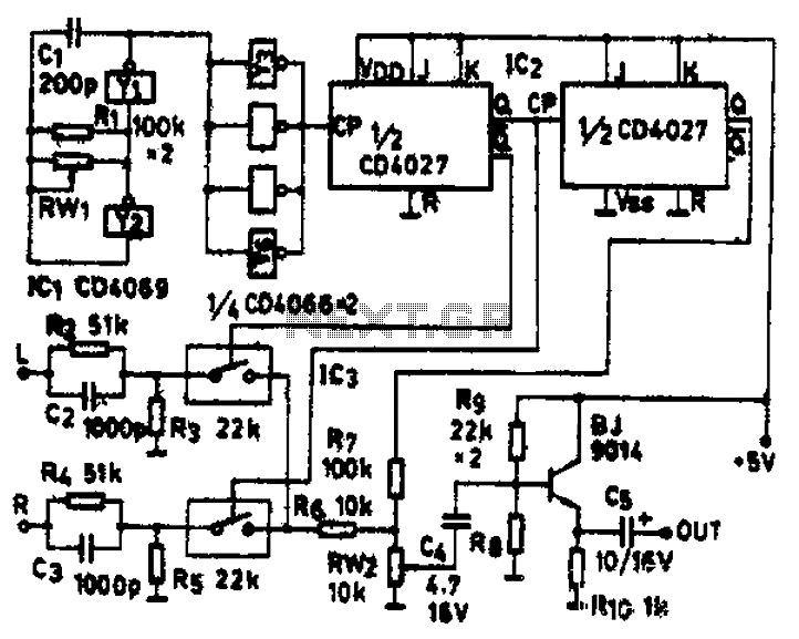
The circuit schematic diagram features IC1 (4069) and components Y1 and Y2, which together form a frequency oscillator operating at 76 kHz. Components Y3 to Y6 provide isolation and shape the output into the IC2 (CD4027) dual JK flip-flop,...