
Triac phase regulator

The operation of the circuit is straightforward. The triac's conduction angle, adjustable via a potentiometer, determines how much of the input sinusoidal waveform is chopped into segments, which can be observed on an oscilloscope. At full conduction, the output resembles a sinusoidal waveform, while at the lowest conduction angle, only the initial portions of the waveform are delivered to the output. The range of regulation is dependent on the load; pure resistive loads begin operating almost immediately from the minimum setting, whereas transformers and similar devices typically require a quarter of the way through the adjustment.
Despite its simplicity, the circuit has minor drawbacks. The smoothness of regulation is load-dependent, and the regulator can generate significant interference in shortwave radio frequencies. If the RC circuit is not properly matched to the specific triac or if an inductive load with loose physical mounts, such as mains transformers with inadequately secured cores, is connected, it may vibrate and produce a growling noise reminiscent of a combustion engine due to the deformed waveform being supplied. It is crucial to avoid regulating capacitive loads or any devices with switched-mode power supplies. In the case of capacitive loads, there is a risk of damaging the triac, while switched-mode supplies may exhibit erratic behavior at reduced output. Examples of capacitive loads include appliances with power factor correction or starting capacitors (e.g., large motors, fluorescent lighting), while switched-mode supplies are commonly found in battery chargers, computer power supplies, CFLs, televisions, and other devices that do not utilize a traditional transformer and operate at voltages different from the mains.
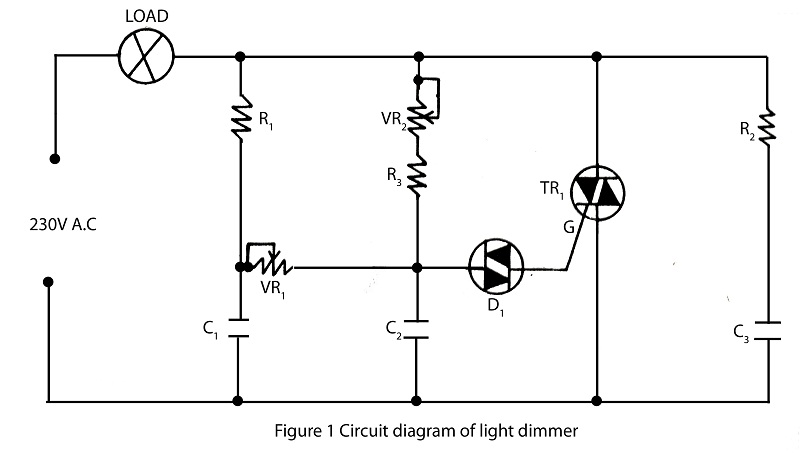
The schematic for this circuit typically includes a triac connected in series with the load, a potentiometer to adjust the conduction angle, and an RC circuit in parallel with the triac to protect against inductive kickback. The potentiometer allows for fine-tuning of the output voltage, while the RC circuit ensures stable operation under varying load conditions. Proper selection of components is critical to optimize performance and minimize interference. The design can be implemented on a printed circuit board (PCB) for durability and reliability in both consumer and industrial environments.This circuit, also informally known as the poor man`s variac, is used in many applications in both consumer and industrial electronics, where a perfectly sinusoidal waveform is not required and a real variac (variable autotransformer) would be too heavy and bulky. This is the case of light dimmers, vacuum cleaners, motor speed control, heater elem ents and similar. It was also one of the first of my creations in the electronics field and has surely helped me along the way. However, the real difference between a circuit like this and a classic light dimmer from your local [insert chain store name here]; is the possibility to regulate also inductive loads.
Basically, cheap commercial SCR- (thyristor) or triac-based dimmers are used for resistive loads only, i. e. incandescent/halogen light bulbs, heater elements etc. With the addition of a protective RC circuit in parallel with the triac to filter out inductive kickback, new possibilities unfold: you are able to regulate fans, mains transformers, vacuum cleaners, drilling machines, angle grinders and the list goes on and on.
The principle is quite simple. Depending on triac`s conduction angle, which is set with the potentiometer, the circuit chops the input sinusoide in segments, this is best viewed on an oscilloscope. At full conduction the output has a sinusoidal waveform; yet the lowest angle yields only its very first portions to the output.
The regulation range itself depends on the load. Pure resistive loads start to work almost directly from the minimum setting onwards; however, transformers and whatnot are working only after e. g. quarter-way through. Despite the simplicity of this circuit, it also has some minor disadvantages. Aside from the load-dependent smoothness of regulation, the regulator makes quite an interference in shortwave radio.
In case of improper RC-circuit matching with your particular triac, or if an inductive load with wiggly physical mounts is connected to the output, for example mains transformers with their cores insufficiently tightened, they might vibrate and make a growling sound, resemblant to that of a combustion engine. This is because the appliance is fed with deformed waveform. Do not try to regulate capacitive loads or anything which has a switched mode supply. In the former case you might short your triac out, in the latter, the supply will behave erratically at throttled output.
Examples of capacitive loads are e. g. appliances with power factor correction or starting capacitors (big motors, fluorescent lighting, etc. ); switched-mode supplies are found in battery chargers, computer power supplies, CFLs, televisions and basically everything, that lacks a classic transformer and works at lower/higher voltages than mains.
🔗 External reference
Related Circuits
The basic clock circuit is similar to the binary clock and uses 7 ICs to produce the 20 digital bits for 12 hour time, plus AM and PM. A standard watch crystal oscillator (32,768) is used as the time...
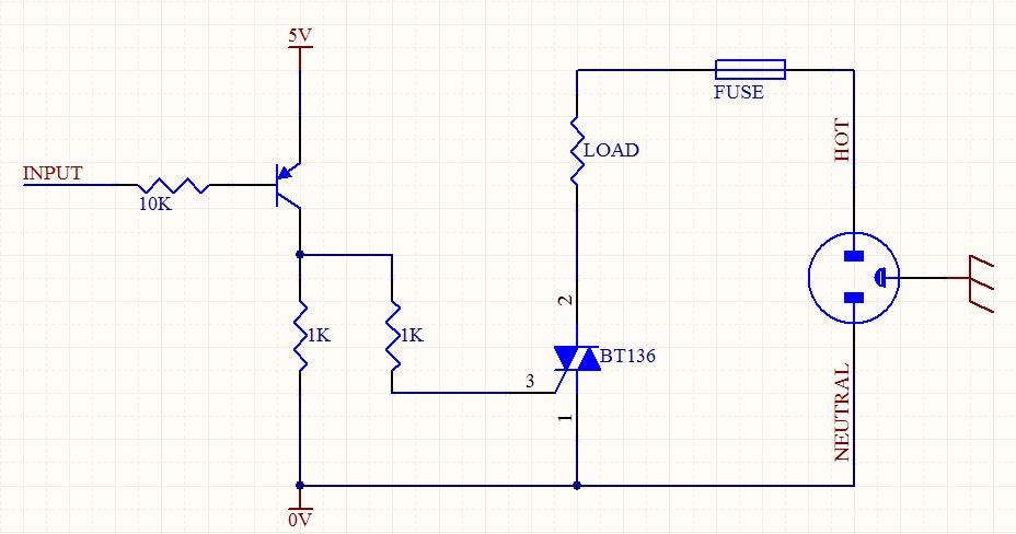
A circuit was designed to function as a light dimmer, utilizing a BT136 SCR and an MOC3022 optocoupler. However, the circuit did not operate as intended. The circuit aims to control the brightness of a light source through phase control...

The LTC3722-1 and LTC3722-2 phase-shift PWM controllers offer all necessary control and protection functions for implementing a high-efficiency, zero voltage switched (ZVS), full bridge power converter. The adaptive ZVS circuitry delays the turn-on signals for each MOSFET, independent of...
The lighting source, such as a bulb or tube light, illuminates based on its specified wattage. To achieve increased brightness, a higher wattage bulb must be used, while a lower wattage bulb is necessary for reduced brightness. However, it...

The SM5023 series consists of 3rd overtone crystal oscillator module integrated circuits (ICs). These ICs are equipped with built-in oscillator capacitors that provide excellent frequency response. The cutoff frequency can be configured using an external feedback resistor (Rfo), allowing...
An integrated voltage regulator connected in reverse to a mini drill allows for speed adjustment within specific limits, maintaining a constant speed regardless of load. The electronic speed control is achieved through a voltage regulator, which can power motors...