
Triggers Circuits

The described circuit employs a photogate and a delay mechanism to accurately capture transient events such as splashes. The photogate operates by emitting a beam of light that, when interrupted by an object, triggers the associated circuitry. The first stage of the circuit involves a 556 timer IC, which contains two 555 timers. The initiation of the first timer occurs upon grounding its input, resulting in a square wave output at pin 5. The pulse width generated is adjustable based on the capacitance selected (C) and the resistance set by the variable resistor (1 MΩ).
The output from the first timer is coupled to the second timer's trigger input through a coupling capacitor (0.005 µF), ensuring that the pulse is transmitted without affecting the timing characteristics. Upon the completion of the first timer's pulse, the second timer activates, producing a short pulse (10 ms) at its output (pin 9). This pulse is critical for controlling a silicon-controlled rectifier (SCR), which acts as a switch to discharge a flash unit, thereby capturing the desired event.
Furthermore, the circuit allows for immediate flash discharge, which can be triggered directly from the first output. The minimal time interval between the immediate and delayed flashes is about 0.2 ms, enabling precise timing control for high-speed events. The interaction between the photogate and the delay circuit is pivotal; the photogate output serves as the delay circuit's input, thus ensuring that the timing can be adjusted based on the specific dynamics of the experiment being conducted.
The selection of the capacitor (C) is crucial for determining the delay duration. For instance, in an experiment involving a droplet of milk falling from a height of half a meter, a delay of approximately 0.3 seconds is required to adequately capture the splash upon impact. By using a 0.5 µF capacitor, the circuit can provide a range of delay times up to 0.5 seconds, allowing flexibility for various experimental conditions. The relationship between the resistance and capacitance values is defined by the formula for time delay, which states that the delay in seconds is approximately equal to the product of the variable resistance in megohms and the capacitance in microfarads. This systematic approach ensures that the circuit can be effectively tailored to meet the needs of different applications in high-speed photography and motion analysis.An advantage that a photogate has over a sound trigger is that the former triggers on the precise location of the object that breaks the beam. For example, the shape of a snapped elastic cord can be photographed as it passes through the beam. While a sensitive sound trigger could also capture the shape, the location of the cord when the flash disc
harged would be much less predictable. A complication when using a photogate occurs if the event to be photographed occurs after the breaking of the light beam. For example, if a liquid drop is to be photographed as it splashes into a pool of liquid, the photogate must be located above the pool.
If the passage of the drop through the photogate were to be the event that triggered the flash unit, there would have to be a delay to allow the drop time to reach the pool. This difficulty can be overcome by using a delay circuit. The delay circuit shown above uses a 556 timer, an IC consisting of two 555 timers. Grounding the input starts the first timer and produces a square pulse at output 1 (pin 5). The width of the pulse is determined by the choice of capacitance, C, and the setting of the 1-M © variable resistor.
Output 1 is coupled to the trigger (pin 8) of the second timer through a 0. 005- µf capacitor. When output 1 falls to zero, the second timer starts, producing a 10-ms pulse at output 2 (pin 9). This pulse gates an SCR to discharge a flash unit. Output 1 can also be used to gate an SCR in order to provide an immediate flash discharge. The smallest time interval between the immediate and delayed discharges is about 0. 2 ms. When using the photogate and delay unit together, the output of the photogate becomes the input of the delay unit. The value of C chosen for the delay circuit depends on the experiment being conducted. If, for example, a drop of milk passes through the photogate and falls a distance of a half meter into a pool, a delay of about 0.
3 s is required to capture the splash. Using a 0. 5- µf capacitor for C provides a selection of time intervals up to 0. 5 s. (The time delay in seconds is approximately equal to the product of the variable resistance in megohms and C in microfarads. ) 🔗 External reference
Related Circuits
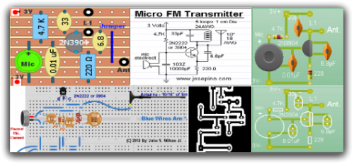
Radio-Circuits has elevated the standard with this website. Unlike any other circuit site on the internet, they have compiled ten of the most popular FM transmitter circuits. Radio-Circuits provides a comprehensive collection of FM transmitter circuits, showcasing a variety of...
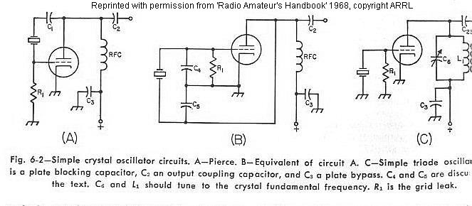
The frequency of a crystal-controlled oscillator is maintained with high precision through the use of a quartz crystal. The frequency is primarily determined by the dimensions of the crystal, particularly its thickness, while other circuit parameters have minimal impact....
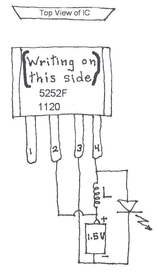
Many Joule Thief circuits traditionally rely on a bulky toroidal inductor that requires careful winding with copper wire. However, there are now compact 4-legged integrated circuits (ICs) available that can perform the same function using only a simple inductor,...
This is a simple yet effective darkness activator. It uses a light-dependent resistor (LDR) to detect light, and when no light is present, it activates an alarm from an 8-ohm speaker. The circuit can be easily modified to function...
This page provides information on circuits that can trigger stroboscopes from external circuits. The circuits are designed to be integrated into stroboscope systems, allowing them to be activated using an external trigger pulse. The standard trigger pulse utilized in...
A simple CATV upstream fiber optic receiver utilizes DC pilot automatic gain control (AGC). Upstream fiber links in a community antenna television (CATV) system are often challenging to align correctly. Set-top boxes and cable modems use "long-loop" AGC. Additionally,...