
555 Circuits

The described circuit primarily revolves around the versatile 555 timer IC, which can be configured in various modes, including astable, monostable, and bistable configurations. The darkness activator utilizes an LDR as a sensor to detect ambient light levels. When light is present, the resistance of the LDR decreases, preventing the 555 timer from triggering the alarm. Conversely, in darkness, the resistance increases, causing the timer to activate and sound the alarm through the speaker.
The power failure alarm aspect of the circuit leverages the voltage behavior at pin 7 of the 555 timer. In normal operation, the voltage at this pin remains high, but in the event of a power failure, the voltage drops, which triggers the alarm output. The metronome function is achieved by configuring the 555 timer in astable mode, where the timing components (resistors and capacitors) set the frequency of oscillation, producing a rhythmic sound.
The Morse code generator functionality is another application of the circuit, where a simple switch press generates a beep corresponding to the Morse code dots and dashes. The missing pulse detector feature ensures reliable detection of input signals by requiring two consecutive pulses to be absent before signaling a missing pulse condition. This is particularly useful in applications where signal integrity is critical.
The touch switch version enhances interaction by allowing the circuit to respond to human presence through static electricity. The 2N2222 transistor amplifies the small current generated by the touch, enabling the circuit to trigger without the need for a mechanical switch.
The inclusion of a switch debouncer is essential for eliminating signal noise caused by mechanical switch contacts. The RC timing circuit ensures that the output pulse remains stable and noise-free during operation. The turn-off delay capability is particularly valuable in automotive applications, ensuring that lights remain on for a predetermined duration after the vehicle is turned off.
Overall, the circuit demonstrates a wide range of functionalities, showcasing the adaptability of the 555 timer IC for various electronic applications, from simple alarms to complex timing and control tasks. Proper selection of component values allows for customization to meet specific operational requirements, making it a versatile tool for electronics design.This is a simple yet effective darkness activator. It uses an LDR to detect the light and when no light is present, it will sound an alarm from a cheap 8Ohm speaker. This circuit can be easily converted to a light detector by simply adding an inverting transistor driver at the output of the 555.
This circuit performs a power failure alarm. It is a 555 oscillator that is off due to the fact that voltage appears at pin 7. When the voltage at pin 7 fails to appear, the alarm will sound from the buzzer. This is a simple metronome circuit that is useful for the friends of music. It will generate the classic toc-toc sound like the mechanical metronomes. The period of the signs can be adjusted from the 250K potentiometer. generator, AKA Morse code generator. The circuit will generate the characteristic `beep` sound of the Morse code generators, every time the switch is pressed. The missing pulse detector is actually a one-shot device that is continuously re-triggered from the input pulse.
The component values for the resistor and the capacitor are to be changed to fit your needs. You should select the parts so that the delay should be about 30-40% bigger than the period of the input pulses. If it is bigger than two input pulses, then in order to detect the input pulse, there must be at least two input pulses missing.
This is a touch switch version of the 555 switch connected as monostable multivibrator. The 2N2222 shall perform an amplifier able to sense slight loads on the plate such as static electricity from the human body. A switch debouncer is a mid-stage block that will clear and square the signal from a push button or a switch.
Those switches are very noisy and the output waveform is filled with noise that will generate false pulses, due to poor contact condition, moisture or dust. [P]The above circuit will generate a noise-free output pules when the button is pressed. This pulse will remain high according to the RC circuit. If the button is pressed further more than the RC time, then the pulse will latch even more. Another use of this circuit is turn-off delay. A big capacitor and a bigger resistor may achieve turn off times like 30sec up to some minutes. This can be for example a car turn-off light delay. [/P] There are several applications that a monostable circuit as the above is used. With very short periods, it could be used as a switch debouncer or a logic driver from fast acting sensors.
Medium periods, like 1-10 seconds could be used for indication sound signals or any other general delay like car cabin lights turn off delay. Bigger periods can be used for delay timers. A 555 can be used to generate clock pulses in a wide range of frequencies with enough output power to drive several ICs.
The oscillation frequency is calculated with the following formula: The same circuit can be used to control DC loads such as LEDs, lamps and DC motors. The idea is to use this circuit as a PWM signal generator. To do this, you need to replace R2 with a potentiometer. By altering the potentiometer`s value, this results in changing the duty cycle output. The duty cycle is calculated as follows: 🔗 External reference
Related Circuits
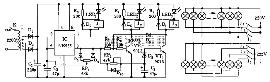
The controller features a buck rectifier circuit utilizing a 555 multivibrator, designed for controlling approximately 220V, 5W low-power parallel lights or 6 to 12V small bulb series. The 555 timer, along with components D3, D4, RP1, and C2, forms...
The curves for a capacitor exhibit significant non-linearity, which can be utilized in circuits to modulate, demodulate, and multiply frequencies. This characteristic is known as non-linear reactance rather than resistance, resulting in minimal energy loss. The charge stored in...
The circuit includes a momentary switch S1 that triggers an alarm pulse for the decade counter IC2, which increments its count with each alternating alarm pulse or the activation of switch S1. Ten variable resistors (VR1 through VR10) are...
555 low power timing circuit diagram. The diagram is from the technical information of Chinaicmart. For more detailed information about the circuit diagram. The 555 timer IC is widely utilized in various applications due to its versatility and ease of...
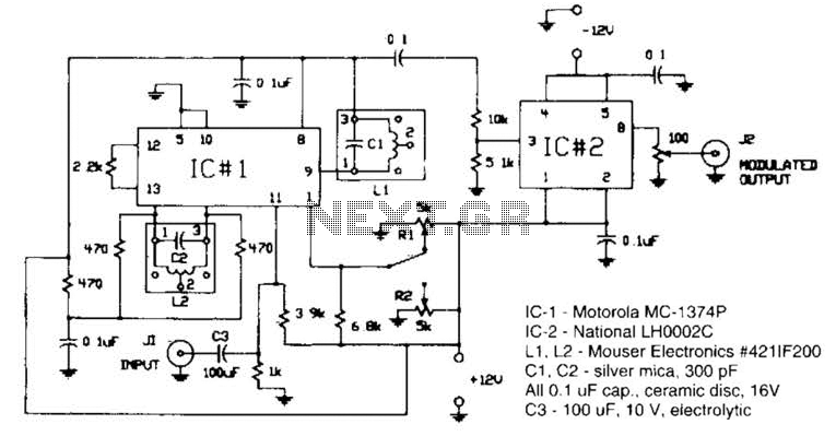
Circuit for applying a DC-coupled FM or PPM to a 555 configured as an oscillator. IC-1 is a Motorola MC-1374P, and IC-2 is a National LH0002C. L1 and L2 are Mouser Electronics #421IF200. C1 and C2 are silver mica...

This circuit is a voltage-controlled oscillator (VCO) that utilizes the 555 timer integrated circuit (IC) as its primary component. The 555 timer is configured as an astable multivibrator, enabling it to function as an oscillator. An astable multivibrator is...