
Tube Compressor

The design of a tube compressor for musical instruments, particularly for bass guitars, typically involves the use of vacuum tubes, such as the ECC83, which are known for their warm sound and harmonic distortion characteristics. The ECC83, also known as 12AX7, is a dual-triode tube that can be utilized in various configurations to achieve desired compression effects.
In a typical tube compressor schematic featuring two ECC83 tubes, one may expect to see the following components and configurations:
1. **Input Stage**: The input signal from the bass guitar is first fed into the circuit, often through a high-impedance input stage to preserve the signal integrity. This stage may include a coupling capacitor to block any DC offset and allow only the AC audio signal to pass through.
2. **Gain Stage**: The first ECC83 tube serves as the gain stage, where the input signal is amplified. The triodes can be configured in a common cathode arrangement to provide voltage gain. Resistors and capacitors are used to set the biasing of the tube and to shape the frequency response.
3. **Compression Circuit**: The signal then passes through a compression circuit, which may utilize a variable resistor or a light-dependent resistor (LDR) to control the gain dynamically based on the input signal level. This stage is critical for achieving the desired compression effect, allowing for a more consistent output level.
4. **Second Gain Stage**: The second ECC83 tube may serve as a make-up gain stage, where the compressed signal is amplified to the desired output level. This stage can also include tone-shaping components such as equalization circuits to enhance the tonal quality of the output.
5. **Output Stage**: The final output stage may include a coupling capacitor to block DC from reaching the output, ensuring that only the AC signal is sent to the next stage, such as a power amplifier or effects chain.
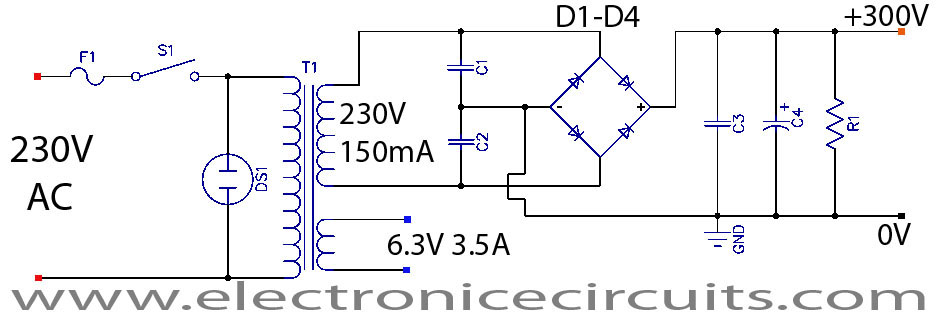
6. **Power Supply**: A suitable power supply is essential for the operation of the ECC83 tubes, typically providing high voltage (around 250V) for the anode and lower voltages for the heater. Proper filtering and regulation are necessary to ensure stable operation and minimize noise.
7. **Additional Features**: Depending on the design, additional features such as a bypass switch, LED indicators, or a blend control for mixing the dry and compressed signals may be included to enhance functionality.
This schematic can be adapted and modified based on specific requirements, such as desired compression ratios, attack and release times, and overall tonal characteristics. Careful consideration should be given to component selection and layout to ensure optimal performance and reliability of the tube compressor.hi i m wanted to start building a tube compressor for my bass guitar , i found a compressor schematic with two ecc83 , but it seems it s too old ,and.. 🔗 External reference
Related Circuits
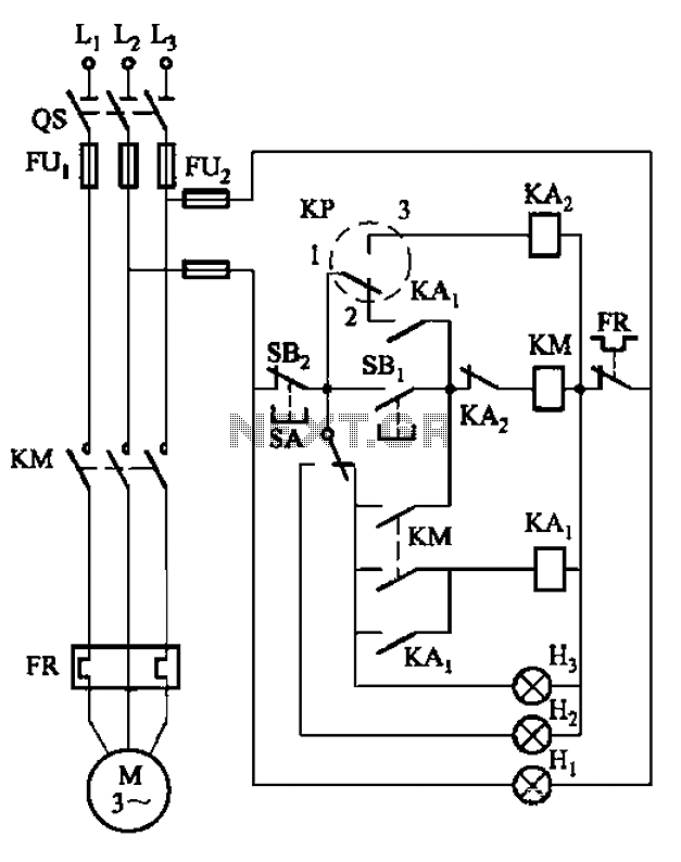
An air compressor is commonly utilized in electrical equipment factories and is typically controlled by electrical contacts. The circuit diagram is depicted in Figure 5-1. The circuit allows for both automatic and manual operation. In the diagram, KP represents...
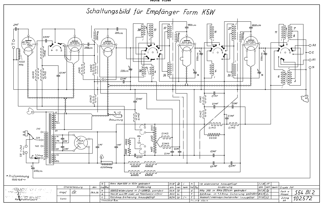
The Nora K5W is a German radio from about 1929/1930. It uses the tubes: 2x REN804, 2x REN1004, RE134 or RE604, RGN1054. The Nora K5W radio receiver represents a significant piece of technology from the late 1920s, showcasing the early...
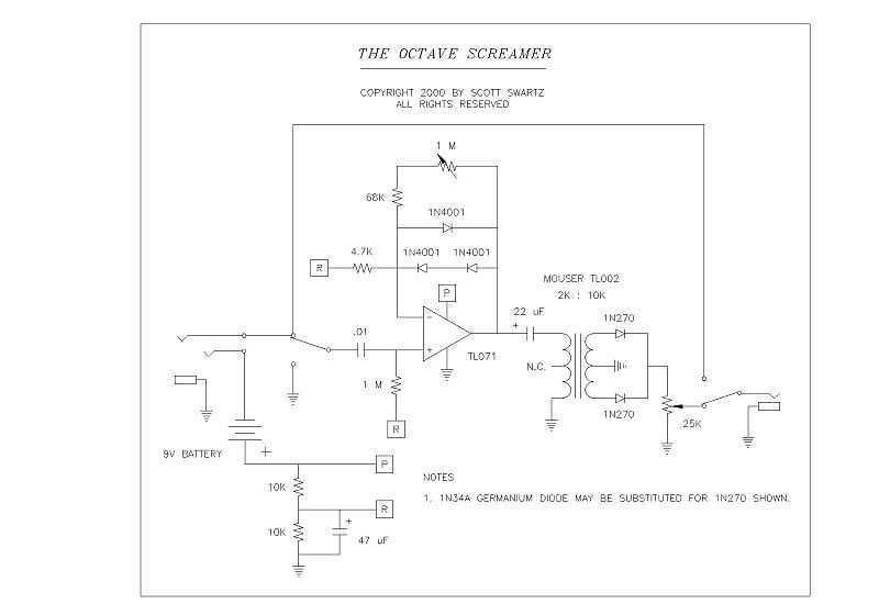
I recently prototyped a Tube Screamer type circuit to refresh my memory about the sound of this pedal. I used a borrowed TS-808 and a Pro Reverb in the mid 80s for several weeks while my modded Twin Reverb...
This is a successful vacuum tube project featuring a small amplifier where a 6V6GT output pentode is connected in triode mode, producing an output of approximately 4.5 watts. The project includes a single-ended audio amplifier with a resistive input...
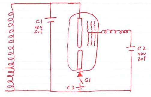
This was not simply shorting out a capacitor through the coil or the tube. However, there is a misunderstanding regarding the functionality of the tube. A discharge is not expected from the low voltage rod to capacitor C2. It...
The following diagram illustrates the circuit design of a 20W power amplifier built using the EL34 tube component. The EL34 is a well-known tube that is highly regarded for its performance in power tube amplifiers. The circuit presented is...