
A-3-7-type air compressor control circuit

The air compressor circuit operates through a feedback mechanism that regulates air pressure effectively. The electrical contacts serve as pressure switches, monitoring the air pressure within the tank. When the pressure exceeds the predetermined upper limit of 0.6 MPa, the closure of contact 13 signals the compressor to stop operation, preventing over-pressurization. This is crucial for safety and equipment longevity.
On the other hand, when the pressure falls below the lower limit of 0.4 MPa, the closure of contacts 1-2 activates the compressor, initiating the air compression process to replenish the tank. This automatic operation ensures that the compressor only runs when necessary, optimizing energy consumption and extending the lifespan of the equipment.
For manual operation, the circuit may include a switch that allows an operator to start or stop the compressor regardless of the pressure readings. This feature is beneficial for maintenance or troubleshooting purposes, providing flexibility in managing the compressor's operation.
The overall design of the circuit should include safety features such as fuses or circuit breakers to protect against electrical faults. Additionally, proper labeling of the contacts and clear wiring diagrams will facilitate easy troubleshooting and maintenance. The use of reliable components, such as pressure switches rated for the specific operational range, is essential to ensure the circuit's functionality and safety.Air compressor (compressor) is commonly used in electrical equipment factory, generally controlled by the electrical contacts. Circuit shown in Figure 5-1. Circuit automatic an d manual operation. Figure, KP as electrical contacts, when the air pressure reaches the upper limit (such as 0.6MPa), the 13 contact closure; when the air pressure starts below the lower limit (eg 0. 4MPa), the contacts 1-2 closure. By the control circuit, the gas tank can always be maintained at a pressure within the range of 0.4 ~ 0.
6MPa required.
Related Circuits
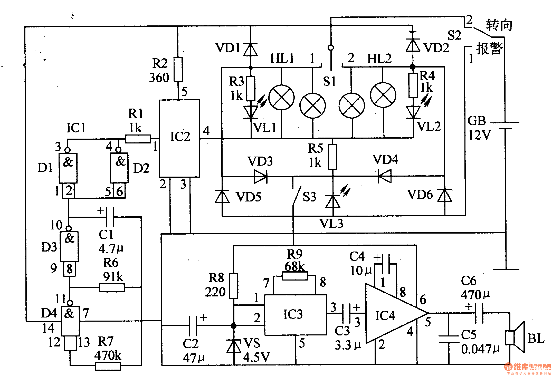
The circuit comprises a low-frequency oscillator, an electronic switch circuit, a control circuit, a photoelectric display circuit, and a music alarm circuit. The low-frequency oscillator is constructed using an integrated circuit (IC) with internal NAND gates and external resistor-capacitor...
A constant speed motor control can be achieved using closed-loop (servo) control. A constant speed motor maintains a steady speed regardless of variations in load. In a closed-loop control system, feedback is utilized to compare the actual speed of the...
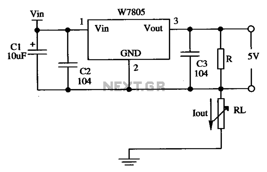
The circuit is composed of a W7805 positive current source application integration circuit that includes a voltage regulator. The W7805 regulator operates in suspension. A resistor is placed between its output terminal and the common terminal, forming a constant...
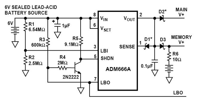
This is a circuit diagram for a solid-state charge detector. It can detect very weak electric fields. The circuit has three components: a 6-volt battery, a light-emitting diode (LED), and a field-effect IC ADM666A. The solid-state charge detector circuit is...
This project began with the exploration of arc starters that could be built at minimal cost using materials typically found in a tinker's workshop. Although it has been an enjoyable endeavor, the extensive collection of items in the basement...
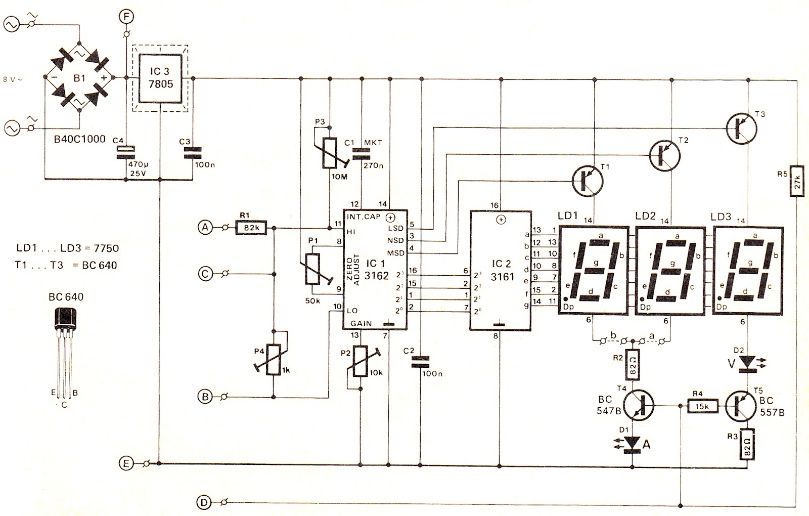
This voltage/current (V/I) display module is well-suited for integration into an existing DC power supply, providing precise readings of the set voltage or the current consumption of the load. The voltage measurement range features a decimal point indicator (LD3),...