
Tube Headphone Amplifier ECC86

This description outlines a triode amplifier circuit based on the EarMax Pro design utilizing ECC86 vacuum tubes. The ECC86 is particularly suited for this application, originally designed for front-end car radios, and operates effectively at an anode voltage of 6V DC, although the circuit is designed for a higher anode voltage range of 48 to 60V, which is considered safe and manageable for less experienced hobbyists.
The circuit is constructed without a printed circuit board (PCB), making it accessible for DIY enthusiasts. The use of a ferrite bead (L1) connected to R1 is critical for radio frequency (RF) suppression, ensuring that the amplifier operates within a frequency range of approximately 20 Hz to well above 1 MHz. Only one channel of the amplifier is described, with a note that the other channel is identical, requiring an additional ECC86 tube for full stereo operation.
The parts list provided includes various resistors and capacitors, all chosen for their specific electrical characteristics suitable for audio amplification. The resistors are primarily 0.6 W metal film types, ensuring precision and stability in the circuit. Capacitors include 22µF and 100nF ceramic types, which are chosen for their reliability and performance in audio applications. The volume control is implemented using a logarithmic potentiometer rated at 100k ohms.
Overall, this amplifier design is straightforward, emphasizing ease of construction and operation while providing high-quality audio output through the use of vacuum tube technology.Because it seemed fun to me also try the so-called "high-end tube technique to highlight here, I agree with some parts from the stock went to work. A second point was that my family had enough of my taste in music that boomed through the speakers. Opted for a triode circuit, based on EarMax Pro, ECC86's. This is a tube that had been designed as a front-end car radios in the serve. With an anode voltage of 6V DC ECC86 still works fine. This design is chosen for an anode voltage of 48 to 60V. This is a safe voltage. Also for less experienced hobbyists. The setup is straightforward, without print, and everyone should be doing. L1 is a ferrietkraaltje connection to a leg of R1. This is necessary for the required RF suppression. The frequency range is ± 20Hz to well above 1MHz. Described only one channel. The other channel is identical and there is an extra ECC86 badly needed. Power for this amplifier is described separately under the heading power. Parts List: R10 = 33 ohm R9 = 150 ohms R6, R7, R8 = 470K ohm R3 = 12k ohm R1, R4 = 220 ohms R2 = 1M ohm R5 = 1k ohm R11 = 22k ohm All resistors 0.6 W metal film C2, C8 = 22? 63V C3, C5 = 22n MKM 1000? C9 = 63V C1, C4, C7, C10, C11 = 100n ceramic C6 = 220? 63V V1a, V2a / b = 2 x 86 ECC P1 = 1 x 100k log. L1 = R1 ferietkraal to leg 🔗 External reference
Related Circuits
This UHF antenna amplifier circuit, also referred to as a UHF antenna booster circuit, is designed to amplify signals within the UHF band, specifically from 400 MHz to 850 MHz. The circuit employs a single transistor and provides an...
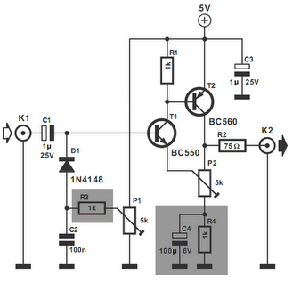
The video amplifier in the diagram represents a well-established design that is both simple and highly functional. However, it is important to note that the transistors can be easily damaged if the potentiometers (black level and signal amplitude) are...
This circuit is designed for use with inductive pick-up elements and dynamic microphones. Most soundcards feature a line input and a dedicated input for electret (condenser) microphones. To connect an inductive tape recorder head or a dynamic microphone, an...
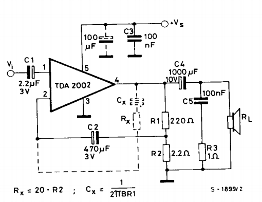
This is a power amplifier circuit built using the TDA2002 power amplifier IC module. It serves as a replacement for the original LM383, which is no longer available. The circuit is easy to assemble and requires a minimal number...
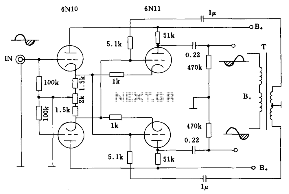
Balanced cross tube inverter circuit, also known as the Chelles inverter circuit, can be utilized as a preamplifier and employs 6N10 and 611 tubes in an inverted configuration. The circuit is designed to work with a final amplifier tube, specifically...
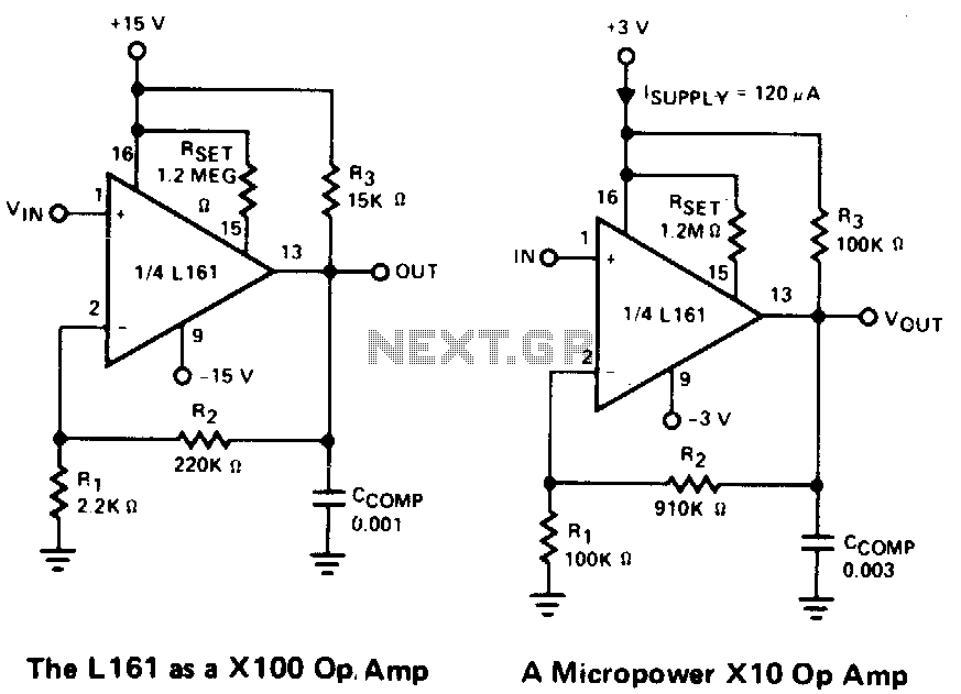
This is a single gain-of-100 amplifier with a gain-bandwidth product of 20 MHz. The primary limitation in performance is the low slew rate of 0.3 V/μs imposed by the charging of Ccomp. The effects of slew rate and compensation...