
tubes williamson
The Williamson Amplifier emerged as a significant advancement in audio amplification technology, particularly in the context of post-war developments in vacuum tube technology. Designed by D.T.N. Williamson in 1947, this amplifier utilized negative feedback to significantly reduce distortion and improve frequency response, addressing many of the shortcomings associated with transformer coupling. The circuit design typically incorporates a push-pull configuration using high-quality vacuum tubes, which allows for greater efficiency and fidelity in audio reproduction.
The Williamson Amplifier circuit is characterized by its use of a phase splitter, usually implemented with a long-tailed pair configuration, to drive the output stage. This design enhances the linearity of the output stage and minimizes distortion. The output stage itself employs a pair of matched power tubes, often operating in a Class AB configuration, which strikes a balance between efficiency and audio quality. The use of output transformers, while still present, is optimized in this design to ensure a wider frequency response and lower distortion levels compared to earlier designs.
The amplifier also features a feedback loop that takes a portion of the output signal and feeds it back to the input stage. This negative feedback reduces the gain but significantly improves the overall performance by flattening the frequency response and minimizing harmonic distortion. The careful selection of components, including capacitors and resistors, further enhances the amplifier's performance characteristics.
Overall, the Williamson Amplifier represents a pivotal development in the evolution of audio amplification technology, setting a standard for high-fidelity audio reproduction that continues to influence amplifier design today. Its design principles laid the groundwork for subsequent advancements in audio electronics, demonstrating the potential of vacuum tube technology when combined with innovative circuit design.A discussion of the Williamson Amplifier should be first preceded by an overview of its context in the evolution of the vacuum tube and its application to high fidelity audio reproduction. Transformer coupling was widely used pre-war because it was simple and effective. It was widely used throughout WWII and later - particularly for public address amplifiers and radio transmitters.
But transformers were expensive, used scarce and expensive raw materials, and performance was generally limited by the transformer characteristics to a frequency response flat from about 20-20, 000 Hz at best and 100 to 5, 000 Hz at worst. Distortion was high due to the use of transformers (low quality by modern standards) and no negative feedback of any kind.
Hum, noise and microphonics would have been barely tolerable. Loudspeakers were improving at a rapid rate and their frequency response capabilities were creating listener awareness of the limitations of the amplifiers of the era. This was a time when large numbers of military personnel were being returned to civilian life and the British economy was in a state of new growth and development.
There was interest, motivation and social approval for people interested in good quality audio to think about it and, if possible, improve their pre-war equipment - by then at least seven years old and most likely much older (a long time in those days). Pre-war valve audio obviously did not include the significant advances made in vacuum tube technology and componentry throughout the world during the war years, so the time was ripe for consumers to upgrade to the benefits of that technology.
Throughout the 1930`s, British valve manufacturers had faced stiff volume and price competition from imports, sourced primarily from the USA. There was much bad blood between the British manufacturers and their US counterparts. One strategy developed by the British Radio Valve Manufacturers Association (BVA) was to attempt to stop all imports of US made valves.
This strategy included agreements with British OEM set manufacturers to use only British TYPES sourced from British factories. Collusive wholesale, trade and retail pricing agreements between the manufacturers ensured that all valves of a similar type or class were priced identically, regardless of manufacture.
At the commencement of war in 1939, the entire British valve industry focused its resources on supplying military needs and much research and considerable development was expended in RF applications to improve frequency, power output and efficiency. This activity led to a proliferation of valve types and numbering systems. The wartime effort resulted in a number of new manufacturers entering the valve market. Mergers and acquisitions were common throughout the war and post-war years through to the mid-fifties, as the British valve industry constantly restructured itself for survival and control of market share.
It was realised that the industry could not defeat competition for imports if it was uncontrolled so attempts began in 1943 to standardise type numbers and rationalise the range of tube types manufactured in the UK to UK designated type numbers only. The situation that applied during the period when Germany occupied Holland is not clear, but one assumes the people at Mullard would have happily exchanged information with their
🔗 External reference
Related Circuits
The use of a quarter-wave parallel-wire line as a tuning unit has been discussed in the chapter on Short Lines, where it was pointed out that these circuits have comparatively high Q even at higher frequencies. Their great length...
This is the unedited version of the article "Improved Anode-Circuit Parasitic-Suppression For Modern Amplifier-Tubes," which was published on page 36 of the October 1988 issue of QST. A subsequent discussion on this topic appeared in the September and October...
This project focuses on the development of a low-cost cosmic ray detector utilizing common fluorescent tubes. It is based on an experiment conducted in 2000 by Dr. Schmeling at CERN, which demonstrated a straightforward method for detecting and visualizing...
The most effective way to understand space-charge tubes is to examine actual circuits. Review the online circuits provided below, and check if any older print articles are available from friends or personal collections. After familiarizing yourself with the material,...
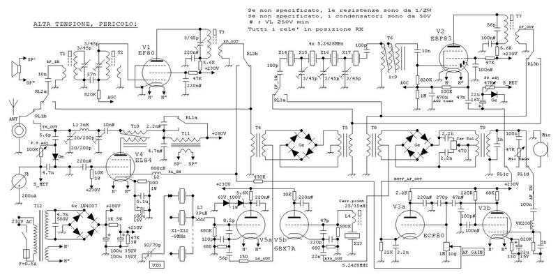
This true SSB transceiver is built around just 5 vacuum tubes, with no transistors nor ICs. Superhet receiver with AGC and S-meter drives a loudspeaker, 5W transmitter, very stable VXO uses CB crystals to cover 20m ham band. A...
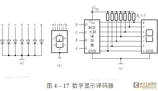
The luminescent diode (LED) is constructed from gallium arsenide (GaAs), a specialized semiconductor material, and gallium arsenide phosphide. It can be used individually or assembled into segment-type or lattice LED display devices. The display unit consists of a sectional...