
Improved Anode Circuit Parasitic Suppression for Modern Tubes

The design and implementation of anode parasitic suppressors in modern amplifier circuits require careful consideration of the evolving characteristics of vacuum tubes. The traditional copper-inductor/carbon-resistor configuration must be scrutinized for its effectiveness with contemporary high-gain tubes. As the amplification factor increases, the likelihood of parasitic oscillations also rises, necessitating a reassessment of the suppressor design.
In modern applications, the suppressor circuit may need to incorporate additional components, such as ferrite beads or tuned circuits, to adequately address the higher frequencies and gains. The parasitic suppressor should be placed as close as possible to the tube's anode to minimize inductive effects and ensure effective suppression of unwanted oscillations. Furthermore, the layout of the PCB should be optimized to reduce parasitic capacitance and inductance, which can significantly influence the performance of the amplifier.
In summary, the evolution of amplifier tubes and their operational characteristics necessitates a reevaluation of traditional parasitic suppression techniques. The application of modern materials and circuit designs can enhance the effectiveness of parasitic suppressors, ensuring stable and reliable operation of high-performance vacuum tube amplifiers.This is the unexpurgated, pre-edited version of the article "Improved Anode-Circuit Parasitic-Suppression For Modern Amplifier-Tubes" that appeared on page 36 in the October 1988 issue of QST. A more recent treatment of the subject appeared in the September and October 1990 issues of QST. The article is titled "Parasitics Revisited. " The purpose in publishing this manuscript is to allow the reader to see whether on not QST is influenced by advertisers. To do this, open up a copy of the Oct. 1988 QST, and compare. Anything in parenthesis is not part of the manuscript text. The information in parenthesis was added later. The traditional copper-inductor/carbon-resistor anode [plate] parasitic-suppressor has been used in vacuum-tube amplifiers for at least 50 years.
The earliest record of an anode parasitic-suppressor that I can locate was in a transmitter that was built in the early 1930s by the (Art) Collins Radio Company. (In late 1990, I was made aware of some interesting information on anode-circuit VHF parasitic suppressors in the 1926 Edition of The Radio Amateur`s Handbook.
This information was inexplicably omitted from post-1929 editions. Info provided by Dave Newkirk, WJ1Z) Much of the reason for Art Collins` early success can be attributed to the fact that he, almost alone, understood that where RF is concerned there is no such thing as a zero-potential "ground" and that any wire or strap was a capacitor-inductor VHF tuned-circuit as well as a conductor. He understood that an "RF-choke" acted like a short-circuit at certain frequencies and that sometimes a resistor would make a better RF-choke than an RF-choke!
Because he understood these "RF secrets", he was the first manufacturer to build a transmitter that: worked on all frequencies up to 14. 5MHz, was stable and could be tuned up every time with no surprises. Anode parasitic-suppressor design has not changed during the last 50+ years while vacuum-tube design has changed markedly.
In the 1930s, 40s and 50s, a "high-Mu triode" had a (voltage) amplification factor of 40. Today, a "high-Mu triode" usually indicates an amplification factor of 100 to 240. A fifty+ year-old parasitic-suppressor design that was usually successful at preventing oscillation in an amplifier-tube with an amplification of 40, may not be as successful on a modern amplifier-tube that has much more gain. Modern amplifier-tubes have another factor, in addition to higher voltage gain, that makes the job of the traditional inductor/resistor VHF parasitic-suppressor more difficult.
That factor is higher frequency capability. Ancient amplifier-tubes could barely be coaxed into amplifying at 28MHz. The 203A that was used successfully in the Collins 150B transmitter had a full-power rating of 15MHz. The popular 8802/3-500Z triode has an average amplification factor of 130 (Eimac) to 200 (Amperex). The Amperex version appears to be electrically equivalent to the 8163/3-400Z with the exception of the anode dissipation rating.
The maximum-input rating of the Eimac 3-500Z, for "radio frequency power amplifier or oscillator service" is 110MHz. 3-500Zs work well above 110MHz if the power is de-rated as frequency increases. Other types of modern amplifier-tubes commonly used in HF-amplifiers have an even higher amplification factor and a frequency rating of up to 500MHz.
The 8874 is a good example of a high gain, 500MHz triode. It has an average amplification factor of 240! This is definitely a high-Mu triode. If an amplifier-tube can amplify at a frequency, it can usually be made to oscillate at that frequency. This is good news for oscillator builders and bad news for unwary amplifier builders. In addition to frequency capability, there are some other prerequisites that must be met before oscillation can be achieved: a feedback path between the output and the input of the amplifier and high-"Q" resonant circuits in the output lead and in the inpu
🔗 External reference
Related Circuits
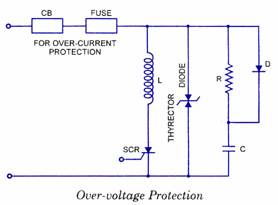
Silicon Controlled Rectifiers (SCRs) are sensitive to high voltage, over-current, and transients. To ensure satisfactory and reliable operation, they must be protected against such abnormal operating conditions. Due to the complexity and cost of protection mechanisms, devices with ratings...
This is a nice design for people who have no tachometer in the car or on the bike. The circuit uses two ICs: an NE 555 and a CA 3140. The input of the circuit is connected to the...
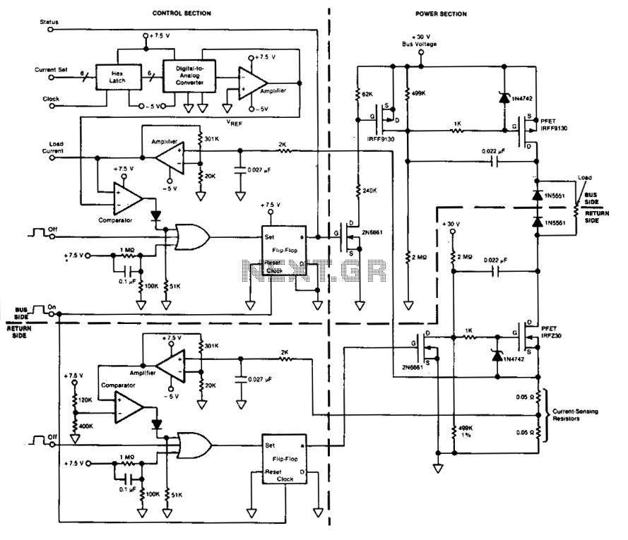
This circuit facilitates on/off switching, soft starting, current monitoring, current tripping, and overcurrent protection for a 30 Vdc power supply, accommodating normal load currents of up to 2 A. The switch is activated by an "on" command pulse and...
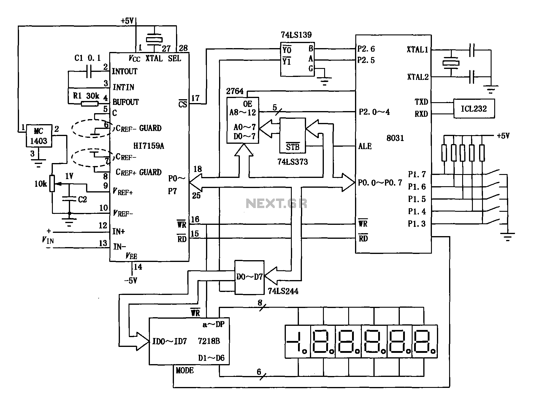
An intelligent digital voltmeter circuit utilizing the HI7159A, 8031 microcontroller, and various other components as illustrated in the figure. The internal circuit incorporates a successive cumulative integrator, digital zero function, low noise BIMOS technology, and other advanced features. In...
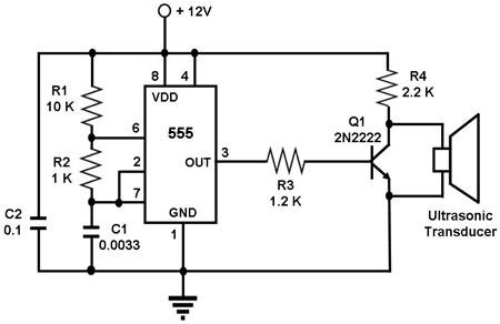
The circuit utilizes a 555 timer integrated circuit (IC) configured as an astable multivibrator, which generates a continuous signal at a specific frequency as long as its reset pin (pin 4) is held high. The ultrasonic transducer employed in...
Construct a low-power FM transmitter using surface-mount devices (SMD) that can be received by a standard FM radio. The proposed low-power FM transmitter circuit utilizes surface-mount devices (SMD) to achieve compactness and efficiency. The primary components of the circuit include...