
Tuned radio frequency receiver

The TRF receiver operates on the principle of selective amplification, where specific frequencies are enhanced while undesired frequencies are attenuated. Each RF amplifier stage is designed to resonate at a particular frequency, achieved through careful tuning of inductors and capacitors in the circuit. The alignment of these components is critical, as even slight deviations can lead to suboptimal performance or instability. The detector stage, often a simple diode or grid-leak detector, plays a crucial role in demodulating the RF signal, converting it into an audio signal that can be further amplified by the audio stage.
In practical applications, the design of a TRF receiver requires consideration of several factors, including the choice of components, layout, and shielding to minimize interference. The physical arrangement of coils and tubes can significantly impact performance, necessitating precise engineering to achieve the desired selectivity and stability. Enthusiasts often experiment with different configurations, utilizing modern materials and techniques to improve upon the original designs.
Despite its challenges, the TRF receiver remains a fascinating subject for radio enthusiasts and engineers alike, representing a significant milestone in the evolution of radio technology. Its historical significance and the principles behind its operation continue to influence modern radio design and experimentation.A tuned radio frequency receiver (TRF receiver) is a radio receiver that is usually composed of several tuned radio frequency amplifiers followed by circuits to detect and amplify the audio signal. A 3 stage TRF receiver includes a RF stage, a detector stage and an audio stage. Generally, 2 or 3 RF amplifiers are required to filter and amplify the received signal to a level sufficient to drive the detector stage. The detector converts RF signals directly to information, and the audio stage amplifies the information signal to a usable level. Prevalent in the early 20th century, it can be difficult to operate because each stage must be individually tuned to the station`s frequency.
It was replaced by the Superheterodyne receiver invented by Edwin Armstrong. The TRF receiver was patented in 1916 by Ernst Alexanderson. His concept was that each stage would amplify the desired signal while reducing the interfering ones. The final stage was often simply a grid-leak detector. The radio schematic above shows a typical TRF receiver. This particular radio uses a six tube design utilizing triode tubes. It has two radio frequency amplifiers, one grid-leak detector/amplifier and three class A` audio amplifiers.
The significance of the term "tuned radio frequency" is best understood when compared to the Superheterodyne receiver. A tuned radio frequency receiver actually tunes the receiver on the true radio frequency whereas the Superheterodyne receiver, tunes the desired signal after conversion to an intermediate frequency.
Many homemade radios constructed by enthusiasts today, are tuned radio receivers, and these can range from single stage to multi-stage receivers. A problem with the TRF receiver is that interelectrode capacitance causes oscillations and other modes in the tuned circuits.
In 1922, Louis Alan Hazeltine invented the neutrodyne circuit, which - as its name implies - neutralizes these capacitances. Antique TRF receivers can often be identified by their cabinets. They typically have a long, low appearance, with a flip-up lid for access to the vacuum tubes and tuned circuits.
On their front panels there are typically two or three large dials, each controlling the tuning for one stage. Inside, along with several vacuum tubes, there will be a series of large coils. These will sometimes be tilted slightly to reduce interaction between their magnetic fields. The primary disadvantage is their bandwidth is inconsistent and varies with center frequency when tuned over a wide range of input frequencies.
This is caused by a phenomenon called the skin effect. At radio frequencies, current flow is limited to the outermost area of the conductor; thus, the higher the frequency, the smaller the effective area and the greater the resistance. Consequently, the quality factor (Q=XL/R) of the tank circuits remains relatively constant over a wide range of frequencies, causing the bandwidth (f/Q) to increase with frequency.
As a result, the selectivity of the input filter changes over any appreciable range of input frequencies. If the bandwidth is set to the desired value for low-frequency RF signals, it will be excessive for high-frequency signals.
The second disadvantage is its instability due to the large number of RF amplifiers all tuned to the same center frequency. High-frequency, multistage amplifiers are susceptible to breaking into oscillations. This problem can be reduced somewhat by tuning each amplifier to a slightly different frequency, slightly above or below the desired center frequency.
This technique is called stagger tuning. The third disadvantage is their gains are not uniform over a very wide frequency range because of the non-uniform L/C ratios of the transformer-cou 🔗 External reference
Related Circuits
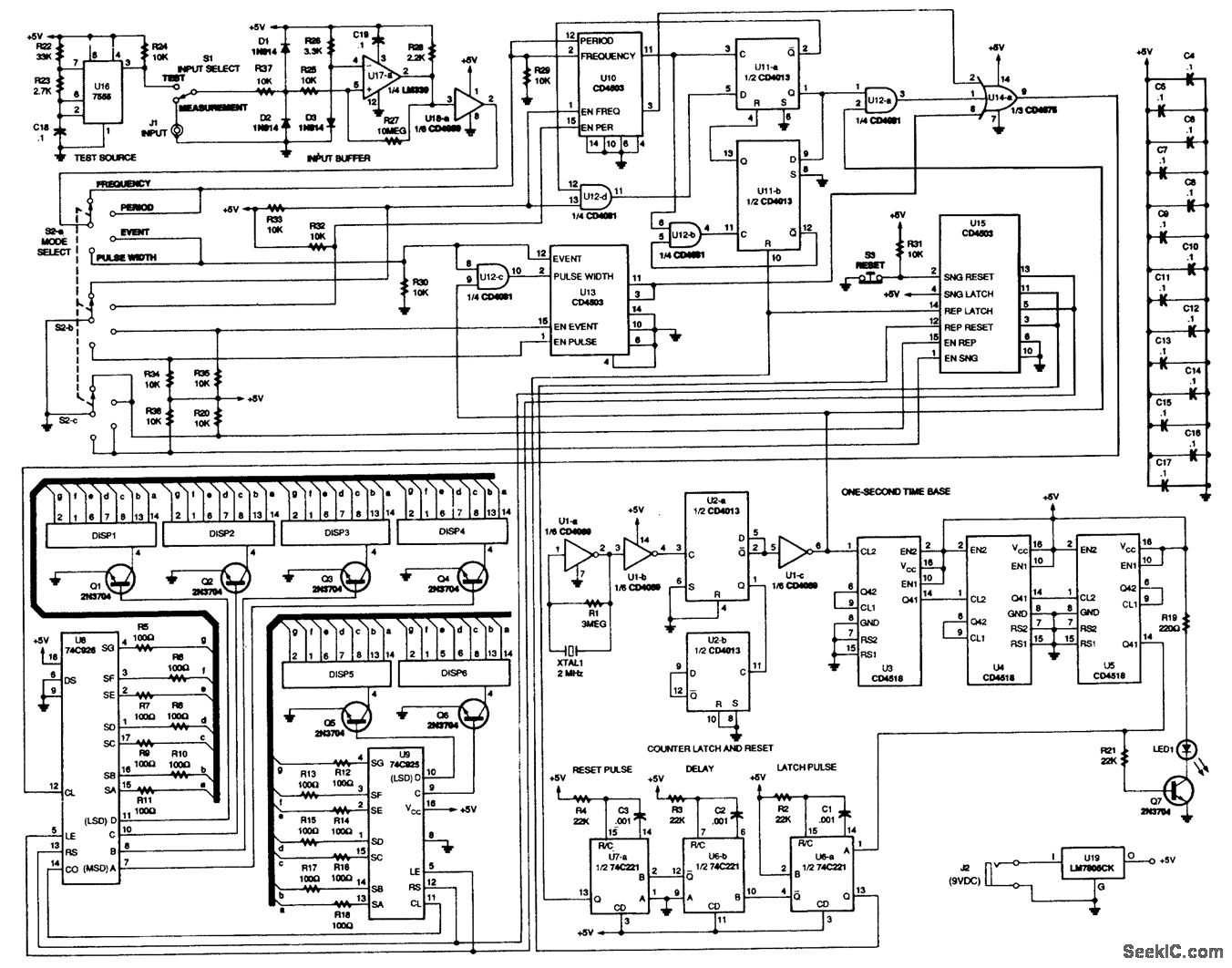
This counter is capable of measuring frequencies ranging from 2 Hz to 1 MHz, as well as time intervals, periods, and counting random events. It utilizes the 74C926 and 74C925 integrated circuits as the primary counting components, which drive...
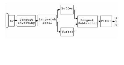
The barrier measurement method for distance is based on assessing the strength of a bound signal. A reflection wave is captured with an acceptor transducer, which emits a sine wave signal. The amplitude of this signal varies with the...
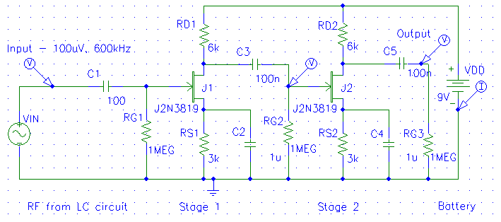
The diagrams below illustrate the development of a simple modular radio receiver based entirely on circuits and devices studied during the Part IA course on Linear Circuits and Devices. This receiver may not revolutionize the market; however, it aims...
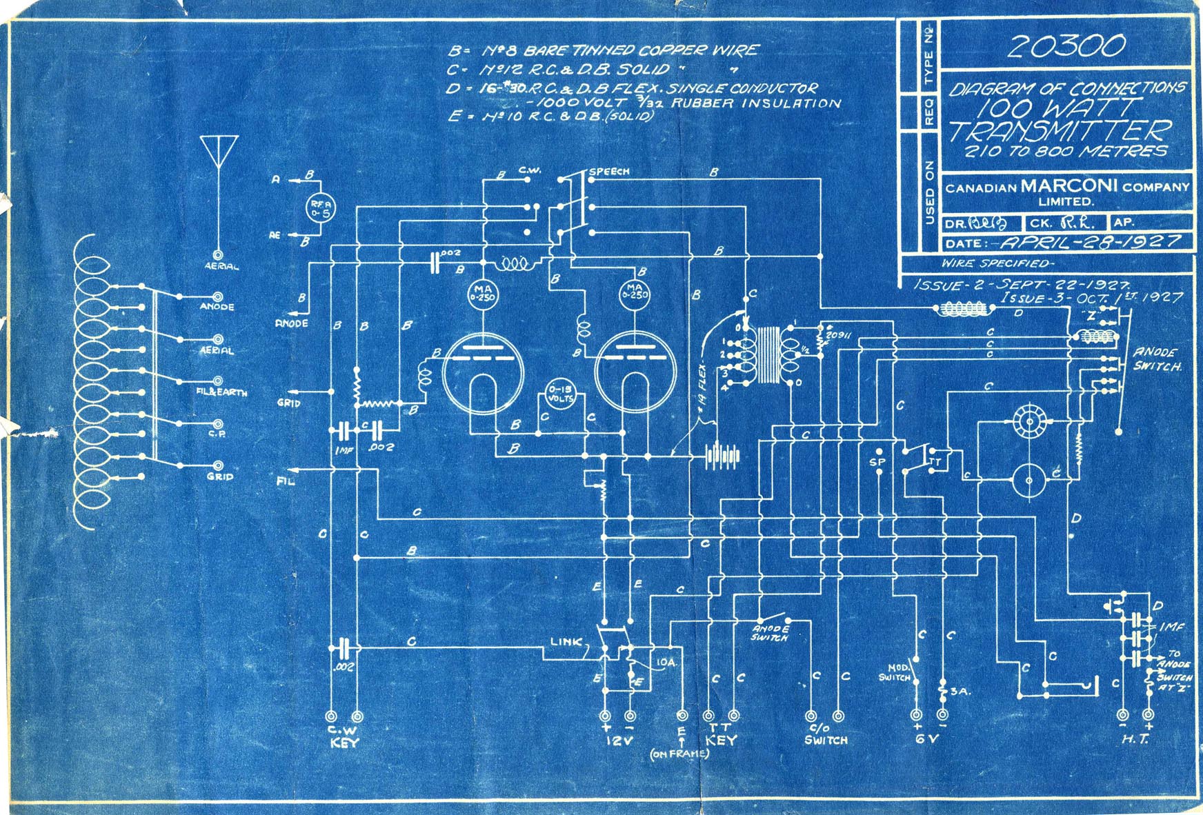
The 100W4 is a two-tube medium frequency transmitter designed for pre-tuning to three frequencies within the medium frequency band, supporting emissions types A1, A2, and A3. In the A1 configuration, both tubes function as parallel oscillators. For A2 and...
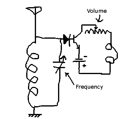
This circuit allows the selection of a station by adjusting the capacitance in an LC circuit. However, the signal remains modulated. To demodulate the signal, a second capacitor is required, but the function of this component is unclear. The...
A line follower robot, abbreviated as LFR, is an autonomous robot designed to optically follow a line drawn on the floor. This involves the robot moving along an arbitrary line using a component known as a line sensor. A...