
ultrasonic receiver

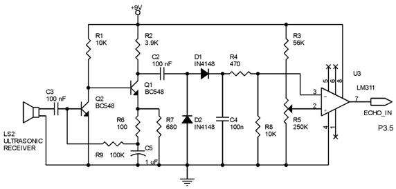
The described electronic circuit for barrier distance measurement utilizes an ultrasonic transducer to detect the distance to a barrier by measuring the strength of the reflected signal. The acceptor transducer plays a crucial role in capturing the reflected ultrasonic waves and generating a sine wave output whose amplitude is directly proportional to the distance from the barrier. The circuit architecture is designed to enhance the signal processing and ensure accurate distance measurements.
The first stage of signal processing involves the inverting amplifier, which amplifies the sine wave signal by a factor of approximately 46. This initial amplification is essential to ensure that the subsequent stages can effectively process the signal. Following this, the precision rectifier circuit is employed, which utilizes operational amplifiers to rectify the AC signal into a DC signal while maintaining accuracy. The gain of this rectifier circuit is designed to be around 2 times, allowing for further enhancement of the signal.
Two buffer circuits are integrated into the design to isolate different stages of the circuit, preventing loading effects and ensuring that the signal integrity is maintained throughout the processing chain. The buffer circuits help in stabilizing the signal levels before they reach the subtractor amplifier.
The subtractor amplifier is utilized to perform a full-wave rectification of the signal, achieving a gain of 1.5 times. This stage is critical for converting the AC signal into a usable DC signal that reflects the distance measurement. The output from this stage is then fed into a low-pass filter designed to eliminate high-frequency noise, with a cutoff frequency of around 60 Hz, ensuring that the final output is smooth and stable.
The final output from the signal adapter circuit is a DC voltage that corresponds to the detected distance, which is then sent to an ADC for digital conversion. This conversion allows for further processing and display of the distance measurement, making the system suitable for various applications in distance sensing. The entire circuit is designed to provide high sensitivity and accuracy, making it effective for measuring distances up to 100 cm with a total amplification of approximately 150 times.Barrier measurement of distance method applied is with measuring strength of bound signal. Reflection wave is catch with an acceptor transducer. Acceptor transducer releases sine signal which the amplitude depended from barrier distance with transducer. Functioning ultrasonic wave Acceptor circuit strengthens, unidirectional and filters output of acceptor transducer before sent to ADC. Signal concurrent done by precision rectifier circuit assisted with two buffer circuit and an amplifier sub tractor to obtain full wave concurrent. Signal adapter circuit will give total reinforcement around 150 times and furthermost barrier distance of which still be detected is around 100 cm.
This picture shows signal adapter diagrams block. Amplifier inverting undertakes as first amplifier with reinforcement value around 46 times. Precision rectifier circuit designed has reinforcement around 2 times. Sub tractor circuit has reinforcement of 1, 5 times. Low filter circuit of order two designed to has frequency value cut-off around 60 Hertz to correspond to requirement. Output of signal adapter circuit is signal DC readily is turned into digital. Picture 5 up to showing each 9 is amplifier circuit inverting, precision rectifier, buffer, amplifier sub tractor and filter applied in this research.
🔗 External reference
Related Circuits
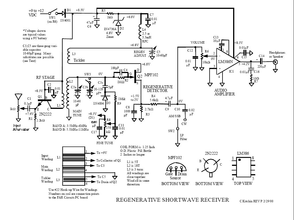
The logical first choice was to start with simple regenerative circuits, utilizing one or two transistors and possibly a basic audio amplifier with a single integrated circuit. A few simple tube radios purchased at flea markets will delay any...
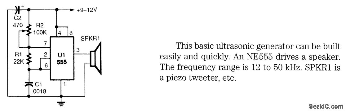
This basic ultrasonic generator can be built easily and quickly. An NE555 drives a speaker. The frequency range is 12 to 50 kHz. SPKRI is a piezo tweeter. The ultrasonic generator circuit utilizes the NE555 timer integrated circuit, which is...
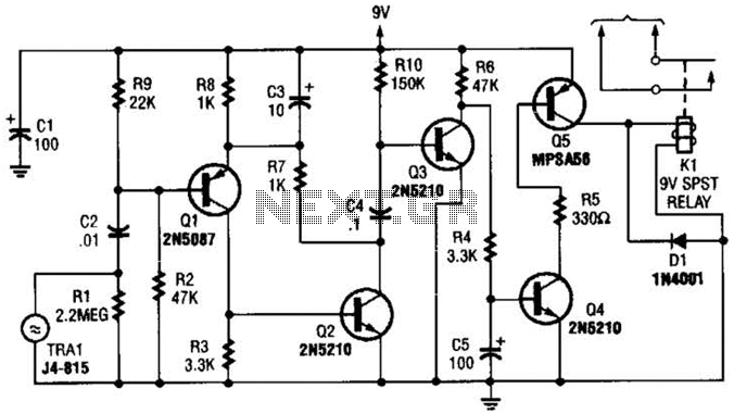
A GC Electronics P/N J4-815 transducer is utilized to receive 40-kHz acoustic remote-control signals. The receiver activates a relay to control another circuit. The GC Electronics P/N J4-815 transducer is designed specifically for the reception of 40-kHz acoustic signals, which...
Techniques for an echo sounder used to measure ocean depth can be implemented with an ultrasonic distance measuring device. This device uses a circuit similar to the one described in the previous article, which includes a series of ultrasonic...
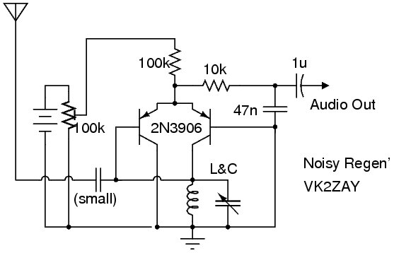
The following circuit illustrates a Noisy Regenerative Receiver Circuit Diagram. Features include a Noisy Regenerative Receiver Circuit, which simplifies the process of... The Noisy Regenerative Receiver Circuit is designed to amplify weak radio frequency signals while also incorporating a regenerative...
The following circuit illustrates an Ultrasonic Sensor Circuit Diagram. This circuit is based on the MAX232 IC. Features include a quiescent current of 150mA. The Ultrasonic Sensor Circuit utilizes the MAX232 integrated circuit, which is primarily designed for converting signals...