
tuned sine wave oscillator circuit

The sine wave oscillator circuit operates by leveraging the characteristics of operational amplifiers to create stable waveforms. The LM111 and LM101A op-amps are configured in such a manner that they can generate both sine and square wave outputs. The tuning of the circuit is primarily achieved through the adjustment of R3, which allows for fine-tuning of the oscillation frequency without altering the overall gain or bandwidth of the circuit.
The feedback loop is critical for sustaining oscillations. The sine wave output generated by the tuned circuit is fed into the comparator, which converts the sine wave into a square wave. This square wave is then reinjected into the input of the tuned circuit, thus reinforcing the oscillation process. The Zener diode, D1, plays a vital role in maintaining a consistent amplitude for the feedback square wave, ensuring that the oscillator operates reliably across its frequency range.
The components R6 and C5 are essential for establishing the initial conditions necessary for the comparator to function effectively. By providing DC negative feedback, they ensure that the comparator remains in the active region, which is crucial for the initiation of oscillation. This configuration allows for a robust and versatile sine wave oscillator that can be employed in various applications requiring precise waveform generation. The design is particularly useful in audio applications, signal processing, and testing environments where a stable frequency output is essential.This is a design circuit for sine wave oscillators that will provide both a sine and square wave output for frequencies from below 20 Hz to above 20 KHz. The frequency of oscillation is easily tuned by varying a single resistor. This circuit is controlled by two op amp, LM111 and LM101A. This is the figure of the circuit. In this circuit, an opera tional amplifier has function as a tuned circuit, driven by square wave from a voltage comparator. The frequency is controlled by R1, R2, C1, C2, and R3, with R3 used for tuning. Tuning the filter does not affect its gain or bandwidth so the output amplitude does not change with frequency. A comparator is fed with the sine wave output to obtain a square wave. The square wave is then fed back to the input of the tuned circuit to cause oscillation. Zener diode, D1, stabilizes the amplitude of the square wave fed back to the filter input. Starting is insured by R6 and C5 which provide dc negative feedback around the comparator. This keeps the comparator in the active region. [Schematic diagram source: National Semiconductor. Inc] 🔗 External reference
Related Circuits

The circuit illustrated in Figure 4 is an AC timing circuit designed to operate for 4 hours. It utilizes the BH4024, a 7-stage serial binary counter/divider, in conjunction with a 555 timer circuit. The circuit is activated by a...
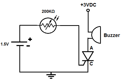
This circuit activates an alarm when tilted beyond a specific angle. Commonly used in various electronic devices, such as heaters, tip-over protection circuits can either shut off the device or trigger an alert. In this case, the circuit is...
If found myself in need of a 1 KHz signal source for an experiments. My function/sweep generator was needed as a pulse generator for the same experiment, so I went though my junk box, looking for circuits from long...

Joule thief circuit along with videos, circuit diagrams, and explanations. The Joule thief circuit is a minimalist boost converter designed to extract energy from low-voltage sources, such as depleted batteries. This circuit is particularly effective for powering small electronic...
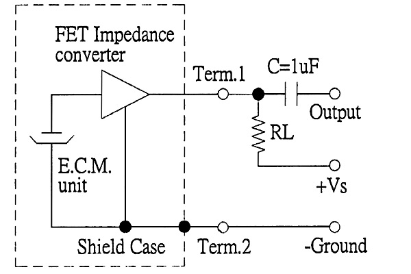
The back of the electret microphone resembles the drawings of the CUI Inc part number CMA-4544PF-W, which will be included in the parts kit. While debugging the data logger software on Windows, an oscilloscope practice lab was conducted using...
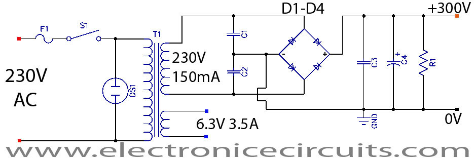
This is a successful vacuum tube project featuring a small amplifier where a 6V6GT output pentode is connected in triode mode, producing an output of approximately 4.5 watts. The project includes a single-ended audio amplifier with a resistive input...