
Turning Stereo Amplifer On and Off automatically

To achieve the desired functionality of automatically turning on an amplifier when music is played, a simple electronic circuit can be designed. This circuit typically employs a sound detection mechanism, which can be implemented using a microphone or a sound sensor module.
The circuit can be structured as follows:
1. **Sound Sensor Module**: A sound sensor, such as the LM393-based microphone module, detects audio signals. This module outputs a high signal when sound levels exceed a predetermined threshold.
2. **Microcontroller**: A microcontroller, like an Arduino or a similar platform, can be utilized to process the output from the sound sensor. The microcontroller will monitor the signal from the sound sensor, and when it detects a high signal indicating sound playback, it will trigger the next stage.
3. **Relay Module**: A relay module is employed to control the power to the amplifier. The microcontroller will send a signal to the relay to close the circuit, thereby allowing electrical current to flow to the amplifier. This will turn on the amplifier when music playback is detected.
4. **Power Supply**: The circuit requires a suitable power supply to ensure that all components, including the sound sensor, microcontroller, and relay, function correctly. Typically, a 5V power supply is adequate for this setup.
5. **Amplifier Connection**: The amplifier is connected to the relay's output. When the relay is activated by the microcontroller, it will complete the circuit, allowing the amplifier to power on.
6. **Adjustable Sensitivity**: It is advisable to include a potentiometer in the sound sensor circuit to adjust the sensitivity of the sound detection, ensuring that the amplifier only turns on in response to desired audio levels.
This circuit provides a straightforward solution for automating the power management of an amplifier based on audio playback, enhancing convenience in home entertainment setups.Do you have an amplifier hidden somewhere in the living room or basement (or home theater) that you want it to turn on when you start to play music?.. 🔗 External reference
Related Circuits
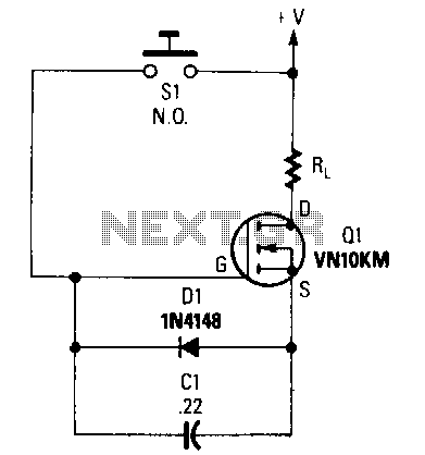
When switch S1 is pressed, capacitor C1 begins to charge to the supply voltage. This action creates a forward bias on the gate of transistor Q1, turning it on and allowing current to flow to the load resistor RL....
The circuit is designed to provide two channels on a stereo mixer intended for microphones, incorporating a crossfader operation. It utilizes the NE5532 integrated circuit. The stereo mixer circuit features two independent channels, each capable of handling microphone input signals....
This is a remote on-off switch circuit. This circuit allows the use of a small switch to control larger AC currents from high-power devices. The remote on-off switch circuit operates by utilizing a low-power control signal to manage a high-power...
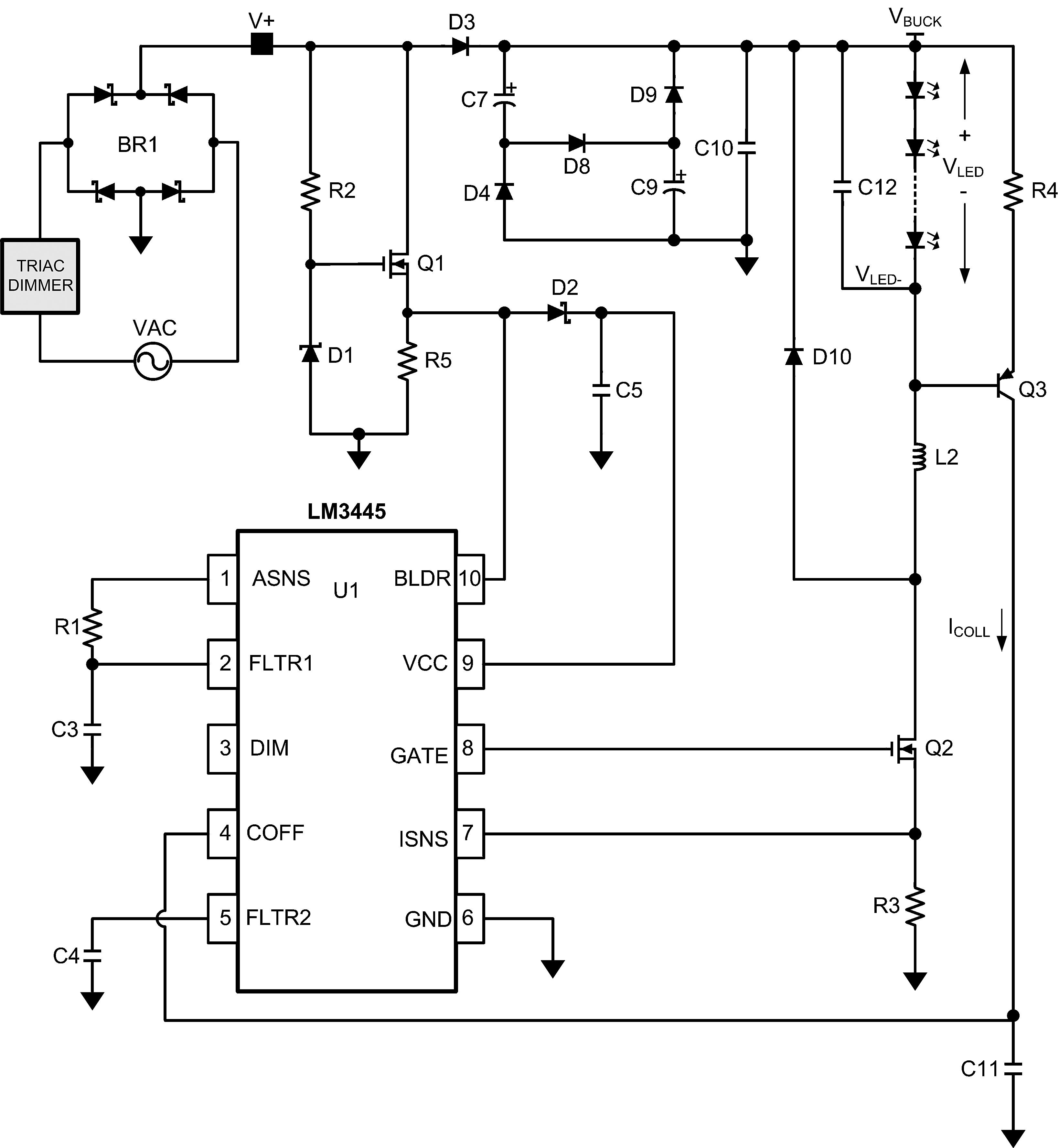
The LM3445 is an adaptive constant off-time AC/DC buck (step-down) constant current controller designed for compatibility with triac dimmers. The LM3445 is a specialized integrated circuit that functions as a constant current controller in AC/DC applications, particularly suited for LED...
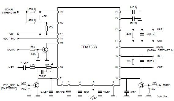
The pilot detector output is configured as an open collector output, requiring an external pull-up resistor. To set the decoder to "MONO," Pin 19 must be clamped to a voltage below 0.8V. The open collector output configuration allows for multiple...
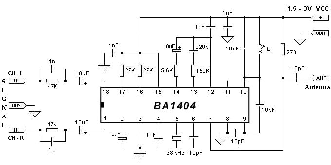
The BA1404 FM stereo modulator IC includes all the necessary components to design a simple, high-efficiency stereo transmitter circuit. It features a stereo modulator that generates composite stereo signals, an FM modulator for creating FM signals, and an RF...