
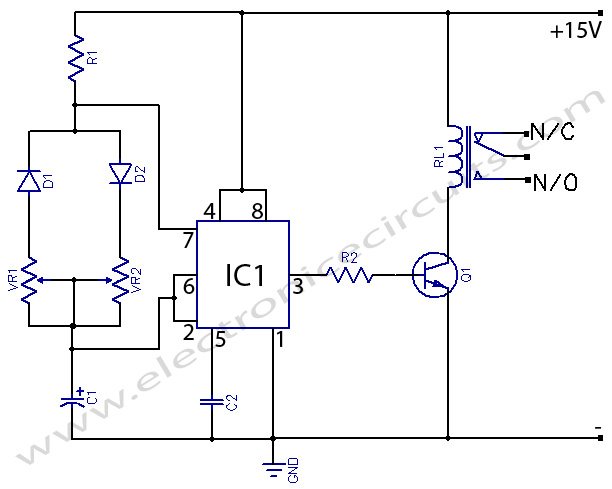
Remote On-Off Switch through Small Transformer

The remote on-off switch circuit operates by utilizing a low-power control signal to manage a high-power load. Typically, the circuit consists of a transmitter and a receiver. The transmitter is connected to a small switch, which can be activated remotely. When the switch is pressed, it sends a signal to the receiver unit.
The receiver is often composed of a relay or a solid-state switch, which is capable of handling the high AC voltage and current required by the connected device. The relay or switch acts as a bridge, allowing or interrupting the flow of electricity to the high-power device based on the control signal received from the transmitter.
Key components in this circuit may include:
1. **Transmitter Unit**: This may consist of a simple RF transmitter circuit that encodes the switch signal and transmits it wirelessly.
2. **Receiver Unit**: This includes an RF receiver circuit that decodes the incoming signal and activates the relay.
3. **Relay**: A relay with appropriate ratings to handle the AC load is necessary. The relay coil is energized by the receiver output, closing the contacts and allowing current to flow to the connected device.
4. **Power Supply**: A suitable power supply for both the transmitter and receiver circuits, ensuring that they operate within their specified voltage and current ratings.
Safety measures should be considered, such as using opto-isolators to separate control and power circuits, and ensuring that the relay is rated for the specific load to prevent overheating or failure during operation. This circuit design is widely used in applications where remote control of appliances is desired, providing convenience and efficiency in managing power consumption.This is a remote on-off switch circuit. With this circuit, we can take the benefit of using small switch to control larger AC current from high power devices.. 🔗 External reference
Related Circuits
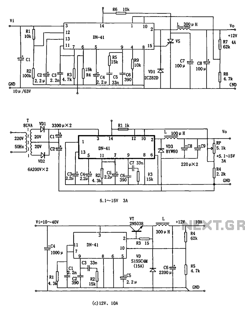
The DN-41 is a high-current switching regulator that includes an overcurrent and overvoltage (crowbar) protection circuit, a reset circuit, and a soft start feature. It is designed to operate with fewer external components while maintaining stability, safety, and reliability....
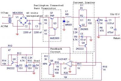
The switching power supply delivers 12 volts at a maximum current of 10 amps, utilizing a discrete transistor regulator with an operational amplifier functioning as a comparator within the feedback loop. The schematic does not depict the front panel...
555 Timer with On-Off Delay Circuit. This circuit utilizes the commonly available 555 integrated circuit (IC) to create a timer that allows for time adjustment in both on and off states. The 555 timer is a versatile device widely used...

This is a simple hobby circuit for a remote-controlled toy car. The primary component utilized is the IR sensor circuit, which includes a TSOP IR receiver. This receiver allows the user to start and stop the DC motor of...
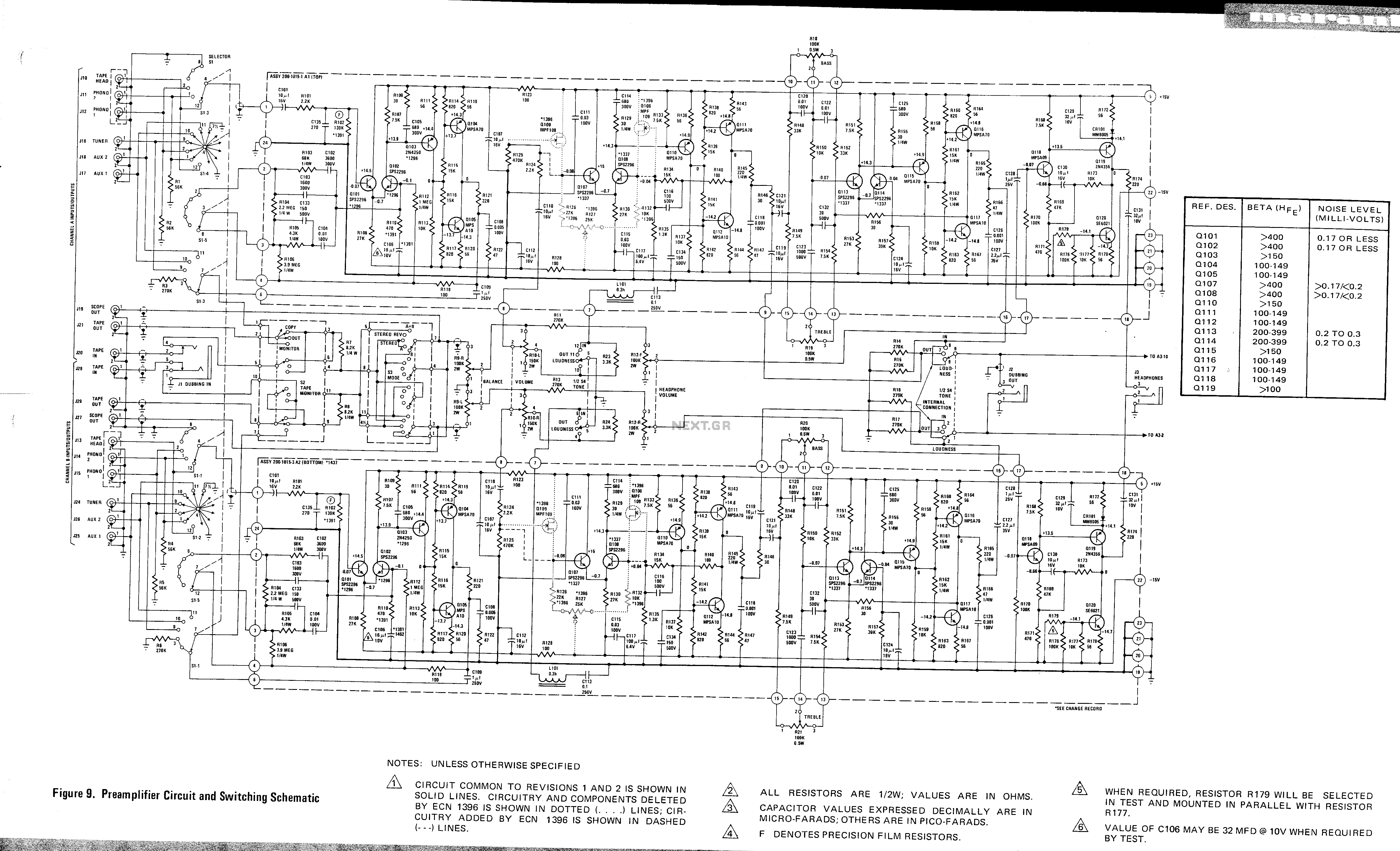
This is a preamplifier circuit and switching schematic for the Marantz Model 33. The Marantz Model 33 preamplifier circuit is designed to amplify low-level audio signals from various sources before sending them to a power amplifier. The schematic typically includes...
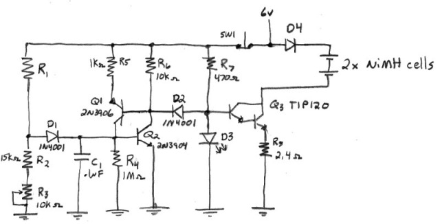
Designing a true constant-current AA NiMH charger requires selecting an appropriate power supply. The voltage must be high enough to prevent the constant current (CC) transistor from saturating, yet low enough to minimize power dissipation in the transistor. The...