
TV LINE DECODER I

The circuit described serves a specific function in television signal processing, particularly in the context of decoding signals for display. The use of CMOS (Complementary Metal-Oxide-Semiconductor) technology is significant due to its low power consumption and high noise immunity, making it suitable for applications in consumer electronics.
The CMOS counter is responsible for counting pulses and generating specific output signals corresponding to the desired TV lines, which in this case are lines 24 and 257. These lines are critical in the vertical synchronization of video signals, ensuring that the output matches the timing requirements of the television display.
Gate logic is employed to control the flow of signals within the circuit. Logic gates, such as AND, OR, and NOT gates, are used to manipulate the binary signals generated by the CMOS counter, determining when the output should be activated. The design may incorporate a combination of these gates to achieve the desired functionality.
The single pin designated for the output line indicator is a crucial aspect of the circuit, as it simplifies the design and reduces the number of connections required. This pin can be connected to an LED or another type of indicator, providing a visual representation of the active output state.
In summary, this circuit is an efficient solution for generating specific outputs in decoder applications, utilizing CMOS technology and gate logic to achieve precise timing and control in television signal processing. The design's simplicity, with only one output line indicator pin, enhances its usability in various electronic applications.This circuit will produce outputs on TV lines 24 and 257. It was used for a decoder circuit. It uses a CMOS counter and gate logic. Only one pin is used for the output line indicator. 🔗 External reference
Related Circuits
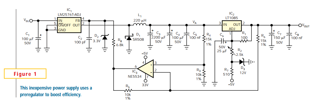
Linear regulators are easy to implement and have better noise and drift characteristics than switching approaches. Their largest disadvantage is inefficiency: excess energy dissipated as heat. Several well-known techniques are available to minimize the input-to-output voltage across a linear...
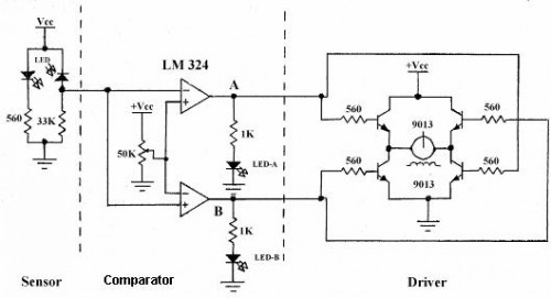
Line follower robots are commonly designed to follow a specific path on a track. Typically, these robots are controlled by microcontrollers; however, this article discusses a line follower robot designed without using a microcontroller. The assembly consists of three...
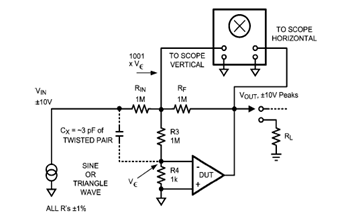
The diagram below illustrates a classic test fixture that has been utilized for an extended period to assist individuals in addressing non-linearity errors. The classic test fixture depicted in the diagram serves as a fundamental tool in electronics testing and...
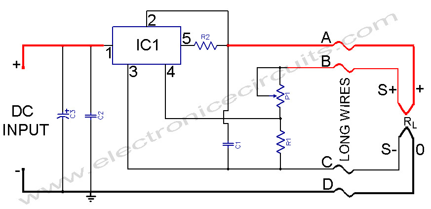
L200 Power Supply Regulator. There are applications in which it is important for the supply voltage to be largely independent of the load level. The L200 is a versatile voltage regulator designed to provide a stable output voltage while maintaining...
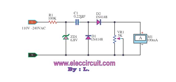
This meter displays the frequency of a power generator, which operates at a voltage range of 110V-240V and a frequency range of 10-100Hz. The output sine waves are converted to square waves. The described frequency meter is designed to accurately...
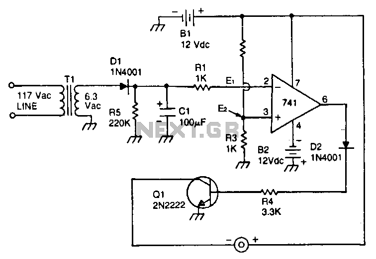
This circuit utilizes a type 741 operational amplifier (op amp) configured as a voltage comparator. One input of the 741 is connected to a reference voltage, sourced from a 12-V battery, via a resistor voltage divider. The voltage at...