
Op Amp Classic Gain and Linearity Testing

The classic test fixture depicted in the diagram serves as a fundamental tool in electronics testing and calibration. It is designed to evaluate and rectify non-linearity errors that may arise in various electronic components and systems. This fixture typically consists of a stable reference signal source, which generates a known input signal, and a measurement system that captures the output response of the device under test (DUT).
Key components of the test fixture may include precision resistors, operational amplifiers, and analog-to-digital converters (ADCs) to ensure accurate signal conditioning and measurement. The setup often incorporates a user-friendly interface, allowing technicians to easily adjust parameters and monitor performance metrics.
The test fixture operates by applying a series of input signals of varying amplitudes and frequencies to the DUT. The output is then measured and compared against the expected linear response. Any deviations from the expected output indicate non-linearity, which can be further analyzed to identify the root cause and implement corrective measures.
In addition, the fixture may include calibration routines and software integration, enabling automated testing and data logging for performance analysis over time. This capability is essential for maintaining the reliability and accuracy of electronic components in various applications, from consumer electronics to industrial systems.
Overall, the classic test fixture plays a crucial role in ensuring the precision and reliability of electronic devices by systematically addressing non-linearity errors, thereby enhancing overall product quality and performance.Diagram below shows you with a classic test fixture that has been used for long periods in order to give anyone for resolving the non-linearity errors for. 🔗 External reference
Related Circuits

A passive high-pass filter has been added after the output of the operational amplifier (op-amp) to eliminate DC offset, with the op-amp powered by +12V and the negative supply at 0V. A feedback resistor (Rf) of 500K Ohms is...
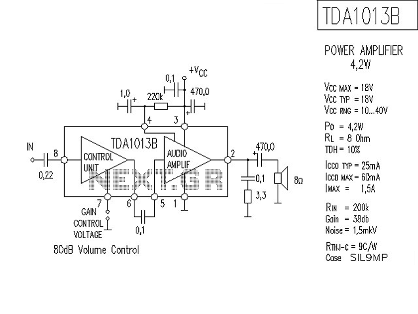
The following is a circuit for a 4-watt audio amplifier. The amplifier utilizes an integrated audio amplifier chip, TDA1013B, which is capable of delivering an audio power output of up to 4W at an 8-ohm load. Its wide supply...
An RF force amplifier for FM is essential for amateurs looking to enhance small transmitters, whether they are homemade or commercially available. The presented circuit can deliver 50-60W of RF power with an input control of 15-20W within the...
The battery voltage is 1V for a low-frequency amplifying circuit, which can operate with a power supply voltage ranging from 1V to 1.7V, making it suitable for use with small batteries. The circuit provides an output power of 80mW...
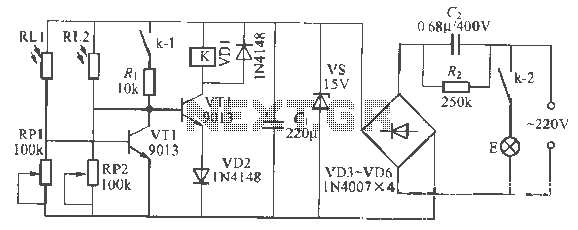
This is a remote-controlled light switch circuit that can be used for remote control toys, flashlight operation, or laser pointers. When the light from a torch illuminates the photosensitive resistor RL2, its resistance decreases, causing transistor VT2 to turn...
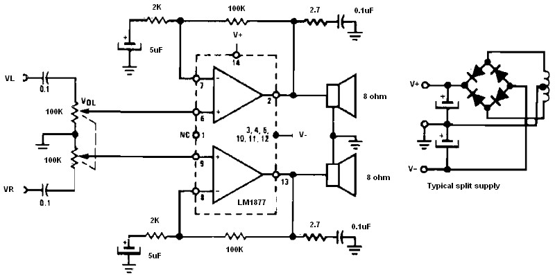
Non-inverting audio amplifier schematic. This non-inverting audio amplifier circuit can be utilized in multi-channel audio systems, stereo phonographs, tape recorders and players, AM-FM radio receivers, servo amplifiers, intercom systems, and automotive products. The audio amplifier described here employs two...