
DIY Homemade Signal Generator with Pulse Width Modulation

To create a versatile signal generator capable of producing square wave signals with variable frequency and pulse width, a configuration based on a 555 timer IC can be employed. The 555 timer, in astable mode, is particularly suitable for generating continuous square wave signals.
The circuit typically consists of the following components: a 555 timer IC, resistors, capacitors, and a potentiometer for frequency and pulse width adjustment. The frequency of the output signal is determined by the values of the resistors and capacitors connected to the timer. To achieve variable frequency, one of the resistors can be replaced with a potentiometer, allowing for manual adjustment.
For pulse width modulation, the duty cycle of the output signal can be manipulated by adjusting the resistance values in the timing circuit. By using a second potentiometer, the pulse width can be varied independently of the frequency, providing greater control over the output signal characteristics.
The output of the 555 timer can be connected to various loads, such as DC motors, lamps, or LEDs, allowing for applications like speed control or dimming. Additionally, the output can be interfaced with high-voltage circuits, such as ignition coils or transformer drivers, by incorporating suitable driver circuits that can handle the necessary voltage and current levels.
To ensure stability and reliability, decoupling capacitors should be placed close to the power supply pins of the 555 timer. A filtering capacitor may also be used at the output to smoothen the signal if required.
Overall, this signal generator circuit is a practical solution for producing adjustable square wave signals for a wide range of electronic applications, making it an invaluable tool for both hobbyists and professionals in the field of electronics.Make a signal generator from easily obtainable parts. Square wave, variable frequency, variable pulse width. This can be used for many things such as DC motor speed control, lamp or LED dimming, Transformer drivers. Ignition coil circuits and other high voltage PSU`s.. 🔗 External reference
Related Circuits
The circuit is straightforward, utilizing a single IC chip, the ICL8038 function generator chip, which produces simultaneous sine, square, and sawtooth waveforms. The circuit consists of a minimal number of components, including two resistors, one transistor, five trimpots, and...
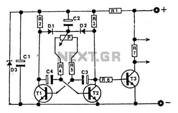
This circuit is designed for controlling motors, lamps, heating elements, and similar devices continuously from nearly zero to maximum capacity (5-95%). It utilizes impulse control for nearly lossless operation, providing almost total torque for motors. The transistor T3 must...
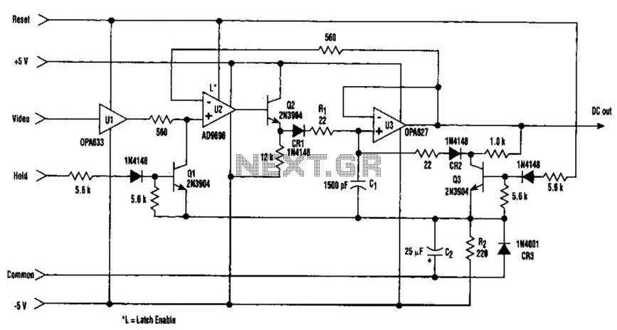
The amplitude of a video signal can be measured using a straightforward circuit that functions as a modified standard peak detector. This device is capable of verifying RGB signals produced by video RAMDACs. U1 is a high-speed buffer, while...
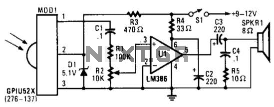
This circuit utilizes an infrared pulse-to-audio converter to assist in troubleshooting infrared remote controls, making it an effective tool for detecting infrared light sources. It employs a photo cell module (Radio Shack P/N 276-137) to detect IR radiation and...
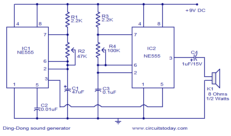
This circuit diagram illustrates a ding-dong sound generator utilizing two NE555 timer integrated circuits (ICs). The design allows for toggling between two adjustable frequencies to create the distinct ding-dong sound. The first NE555 (IC1) is configured as an astable...
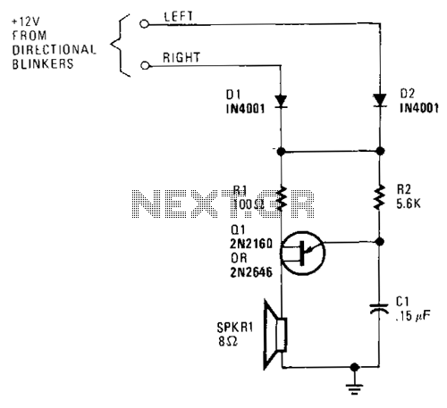
A unijunction transistor audio oscillator drives a small speaker. The oscillator's frequency is determined by resistor R2 and capacitor C2. The operating voltage is supplied from the car's turn-signal circuit(s) through D1 and D2. The diodes conduct current from...