
tv transmitter and pal video modulation

The described TV transmitter circuit operates by employing negative sound modulation alongside PAL (Phase Alternating Line) video modulation techniques. The circuit is designed specifically for compatibility with television broadcasting standards B and G, which are commonly used in several regions worldwide.
Inductor L1 is a crucial component in this circuit, serving as a part of the oscillator circuit. It can be fabricated using 24 SWG (Standard Wire Gauge) wire, wound into a coil with four turns and a diameter of 6 mm. This specification allows for the appropriate inductance required for the modulation process, ensuring that the transmitter operates efficiently within the desired frequency range.
Transformer T1 plays a vital role in the circuit by facilitating the transfer of energy between the transmitter and the antenna. This transformer should be selected carefully; an ideal choice would be an RF transformer that includes an internal capacitor, as this can help in tuning the circuit to the required frequency. Such transformers are often salvaged from older transistor radios, making them accessible for DIY projects.
The overall design emphasizes simplicity, making it suitable for hobbyists and engineers looking to experiment with television transmission technology. The use of readily available components, such as wire for the inductor and transformers from obsolete devices, underscores the practicality of this circuit. Proper assembly and tuning of the transmitter will yield a functional device capable of transmitting television signals effectively within the specified standards.The following is a series of simple TV transmitter using negative using sound modulation and PAL video modulation. This is suitable for countries using TV systems B and G. Inductor L1 can be made by wire email (24SWG) 4 convolution with 6mm diameter and T1 can be used with a radio frequency transformer internal capacitor.
(Can be found on the old transistor radios). 🔗 External reference
Related Circuits
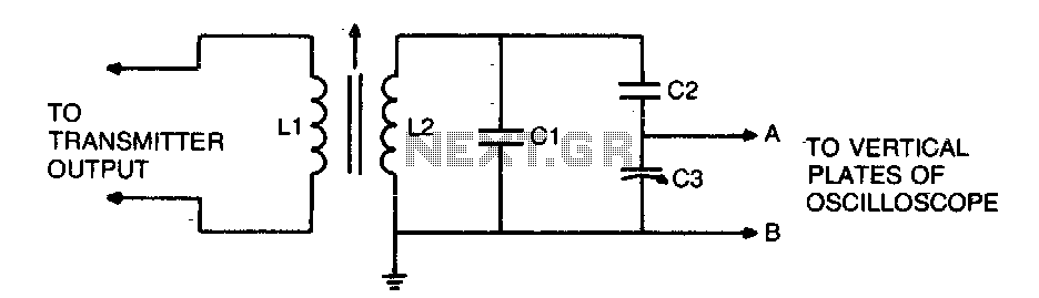
To display an RF signal, connect LI to the transmitter and points A and B to the vertical plates of the oscilloscope. Adjust LI for minimum SWR and C3 for the desired trace height on the CRT. More: L2...
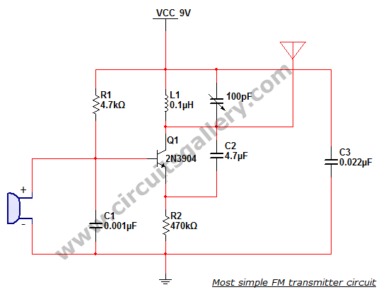
This is the simplest single transistor FM wireless transmitter circuit ever posted in CircuitsGallery. In the field of telecommunications, frequency modulation (FM) transmits information by altering the frequency of a carrier wave based on the message signal. FM utilizes...
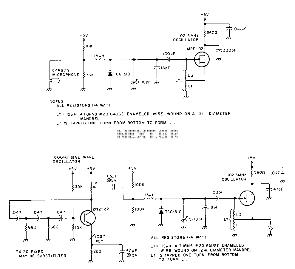
The 2N2222 circuitry is a three-element, phase-shift oscillator circuit designed to produce a 1,000 Hz sine wave. This sine wave is applied to the TCG-610 varactor diode, which has a capacitance of 6 pF at 4 V. This application...
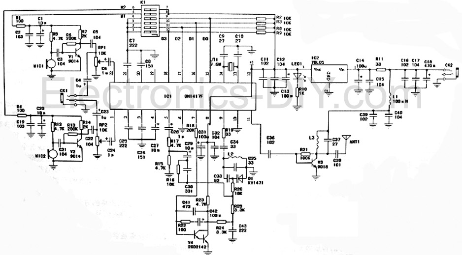
This is a high-fidelity stereo PLL FM transmitter designed for various audio sources including computers, sound cards, game consoles, CDs, DVDs, MP3 players, and stereo mixers. The board features two microphone amplifiers, enabling high-fidelity FM stereo radio transmission when...
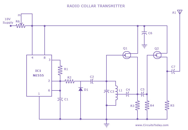
This is a radio transmitter circuit diagram designed for integration into radio collars using the NE 555 integrated circuit. The circuit transmits a pulse in the FM band, specifically between 88 MHz and 105 MHz. The radio transmitter circuit utilizes...
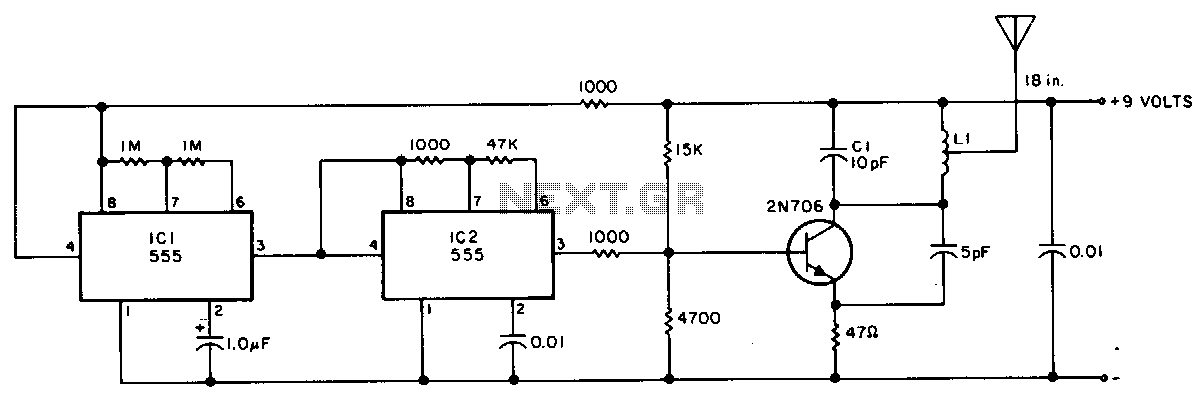
This transmitter is suitable for transmitter hunts, remote key finding, or radio telemetry in model rockets. It can be tuned to the two-meter band or other VHF bands by adjusting capacitor C1 and inductor L1. L1 consists of four...