
Transmitter-oscilloscope coupler for CB signals

The circuit described is an RF signal display setup that utilizes an oscilloscope to visualize the signal characteristics. The primary component for signal pickup is LI, which is connected to the transmitter. This inductor is critical for ensuring a proper match between the transmitter and the load, which is achieved by adjusting LI to obtain the minimum Standing Wave Ratio (SWR). A lower SWR indicates better efficiency in power transmission and lesser reflections.
The oscilloscope's vertical plates, connected to points A and B, allow for the visualization of the RF signal. The adjustments made to C3, a 75 pF trimmer capacitor, facilitate the fine-tuning of the trace height on the cathode-ray tube (CRT), ensuring that the signal is displayed clearly and within the desired range on the screen.
The circuit also includes L2, which is constructed with 4 turns of #18 wire wound on a %" slug-tuned RF coil form. This component serves as a resonator, helping to filter and select the desired frequency range of the RF signal. The use of a slug-tuned coil allows for easy adjustments to the inductance, enabling precise tuning to the operating frequency.
Additionally, LI consists of 3 turns of #22 wire, positioned adjacent to the grounded end of LI. This configuration is essential for establishing the correct coupling between the inductor and the RF signal source, optimizing the signal transfer to the oscilloscope. The capacitors C1 and C2, each rated at 5 pF, are likely used for impedance matching or filtering purposes within the circuit, ensuring that the signal integrity is maintained throughout the system.
Overall, this schematic provides a comprehensive approach to displaying RF signals, emphasizing the importance of component selection and configuration in achieving optimal performance in RF applications.To display an rf signal, connect LI to the transmitter and points A and B to the vertical plates of the oscilloscope. Adjust LI for minimum SWR and C3 for the desired trace height on the CRT L2 = 4 turns #18 on %" slug tuned rf coil form, Ll = 3 turns #22 adjacent to grounded end of Ll, Cl, and C2 = 5 pF, C3 = 75 pF trimmer.
Related Circuits
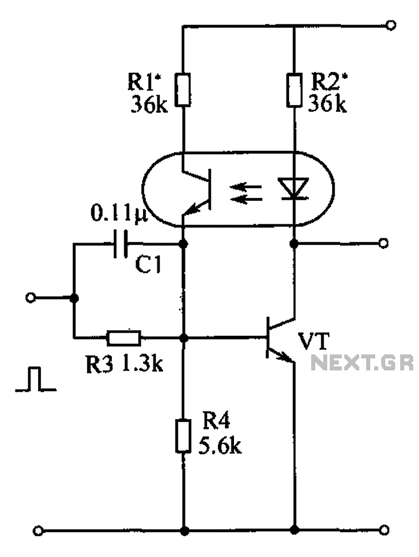
The bistable circuit and optocoupler transistor operate as illustrated in the accompanying figure. Initially, when the supply voltage is applied, the transistor VT is in the off state, resulting in a high output potential. Upon receiving a forward pulse...
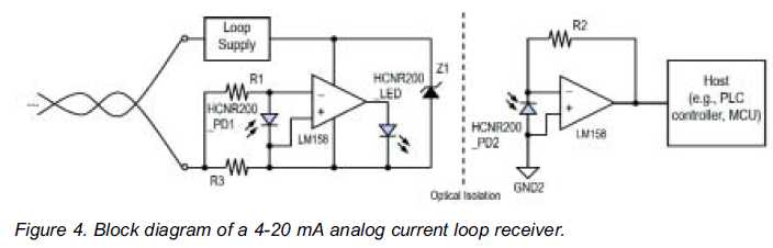
High linearity analog optocouplers offer the versatility needed to address a variety of analog isolation requirements. For high voltage applications, these optocouplers can effectively transmit analog signals between high voltage and low voltage areas without introducing distortion. This article...
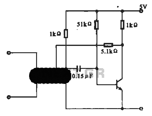
This circuit illustrates an oscillator that is controlled by an optocoupler, utilizing photoelectric coupling to drive a transistor. The oscillator circuit described operates by employing an optocoupler to provide electrical isolation between its input and output stages while allowing control...
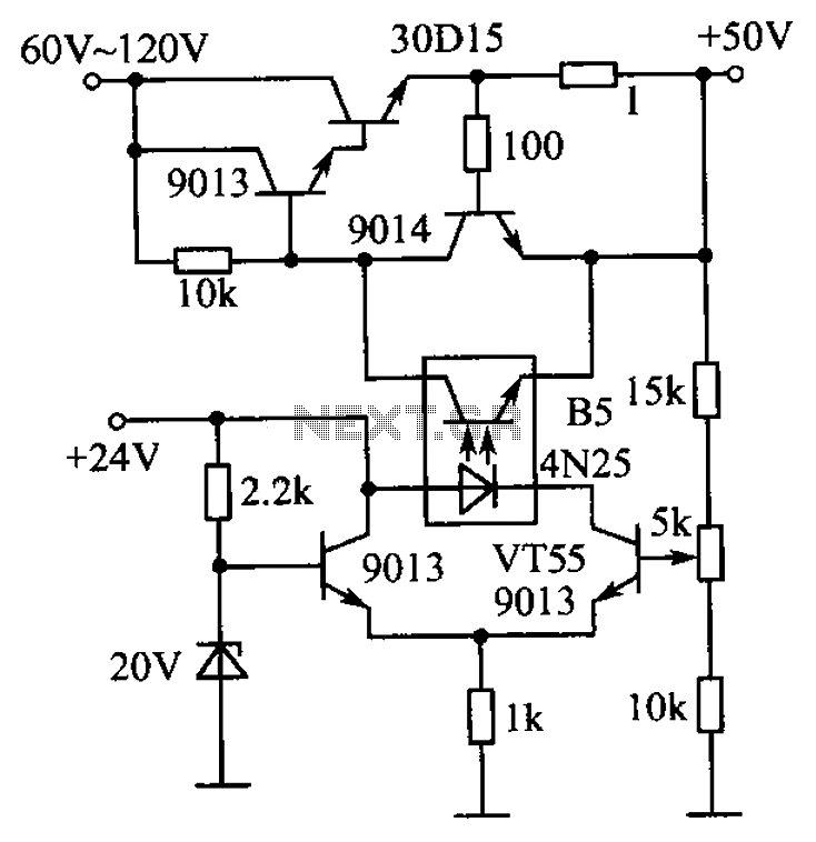
The circuit is illustrated. A standard driving transistor requires a higher breakdown voltage transistor (such as the FIG driving tube 9013). As the output voltage rises, the bias on VT55 increases, leading to an increase in the forward current...
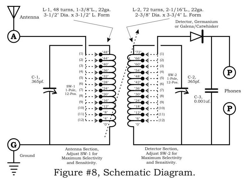
A two-circuit tuner, similar to a loose coupler, is an effective method for achieving selectivity without compromising sensitivity. The circuit introduces the signal to the primary antenna section via the SW-1 arrangement, allowing the antenna to be matched to...
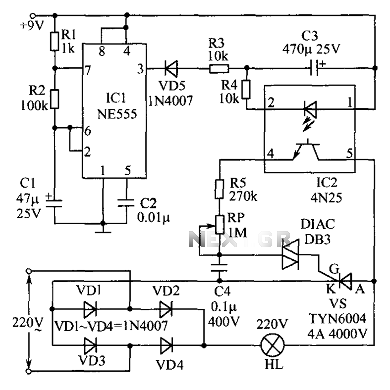
This circuit features an appealing Christmas lights setup. Upon activation, the lights (HL) gradually increase in brightness. Once they reach maximum brightness, they automatically dim, and upon reaching the lowest brightness, they gradually brighten again, creating a smooth transition...