
Two Colour LED Light Bar Circuit Schematic Diagram

This circuit design employs a 2-color LED that alternates between two distinct colors, creating a visually appealing light effect. The core of the circuit utilizes a NAND gate configuration, specifically the 4011 series, which is a versatile component in digital electronics. The NAND gates are responsible for generating the necessary logic signals that control the timing and sequencing of the LED states.
The frequency of the LED color alternation is determined by the resistor-capacitor (RC) network formed by R2, R3, and C2. The values of these components can be adjusted to modify the blinking rate, allowing for customization based on user preference or application requirements. This flexibility is essential in applications where visual signaling or decorative lighting is desired.
The output from the NAND gates (IC2 and IC3) is connected to the LED display. The configuration ensures that the output signals are appropriately timed to illuminate the LEDs in a synchronized manner. The connection to the JK flip-flop (IC4) adds an additional layer of control, allowing for the toggling of states based on the input signals received at pins 1 and 3. This integration of flip-flop technology enables the circuit to maintain its state until a reset condition is triggered.
The circuit's design also emphasizes modularity, as it is divided into three distinct sets: gesture generators, a parade, and control. This modular approach allows for easier troubleshooting and potential expansion of the circuit functionality in future iterations.
Overall, this two-color LED light bar circuit exemplifies a practical application of digital electronics, combining logic gates, counters, and flip-flops to achieve a dynamic lighting effect suitable for various uses, from decorative displays to signaling applications.This circuit is a circuit run on alternating two insignia. It uses the 2-color LED with a built-participating in 3-pin single. This preference look for away the glow of every LED until the base. It turns alternating to one more color. In in the least way to the moon on the moon essential end, afterward the LED end of the first LED. Circuit consists of, nand gate ic. Two 10 Counter circuits IC, and IC JK flip washout. company of the circuit is not speaking into 3 sets. It is a solid of gesture generators, a set of parade and control. Set the signal generator is IC1a, and IC1b quantity 4011 is a signal generator. The R2, R3, C2 determine the frequency generated. The hint is fed to a set of impressions is the figure 4011 IC2 and IC3. The 10 counter circuits to output to the LED, and Is the same, but the effort should ensue performed individual by the side of region. Therefore, the show from pin 11 of IC 2 and tested pro D2 and D3, To pin 3 of IC4. The integrated circuit IC 4 is a JK flip slump is connected to a T flip flop. The signal input pin 3 and pin 1 is the output hint at. Which sends a signal to the Reset IC either obstruct working. IC4 on the anniversary, it want output the originally moment in time, happening contrast to pin1. IC3 progress to handiwork, IC2 stopped. You are reading the Circuits of Two Colour LED Light Bar Circuit And this circuit permalink url it is
🔗 External reference
Related Circuits
The thermocouple cold junction compensation circuit and the MAX6675 converter circuit diagram form a temperature measuring system. The system utilizes a K-type thermocouple connected to the T terminals of the MAX6675, with the cold junction grounded. An 8051 microcontroller...
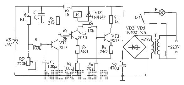
The circuit operates as a light-activated switch that controls white moving lights. It features high sensitivity, stable performance, and good anti-interference characteristics. A photosensitive resistor (RI) is employed to detect ambient light levels. During the day, the resistor exhibits...
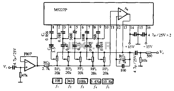
The M5227P is an application circuit designed for a graphic equalizer. Its control curve operates on a logarithmic frequency axis to represent the rate, requiring the same control curve pitch to ensure that all bands achieve maximum lift or...
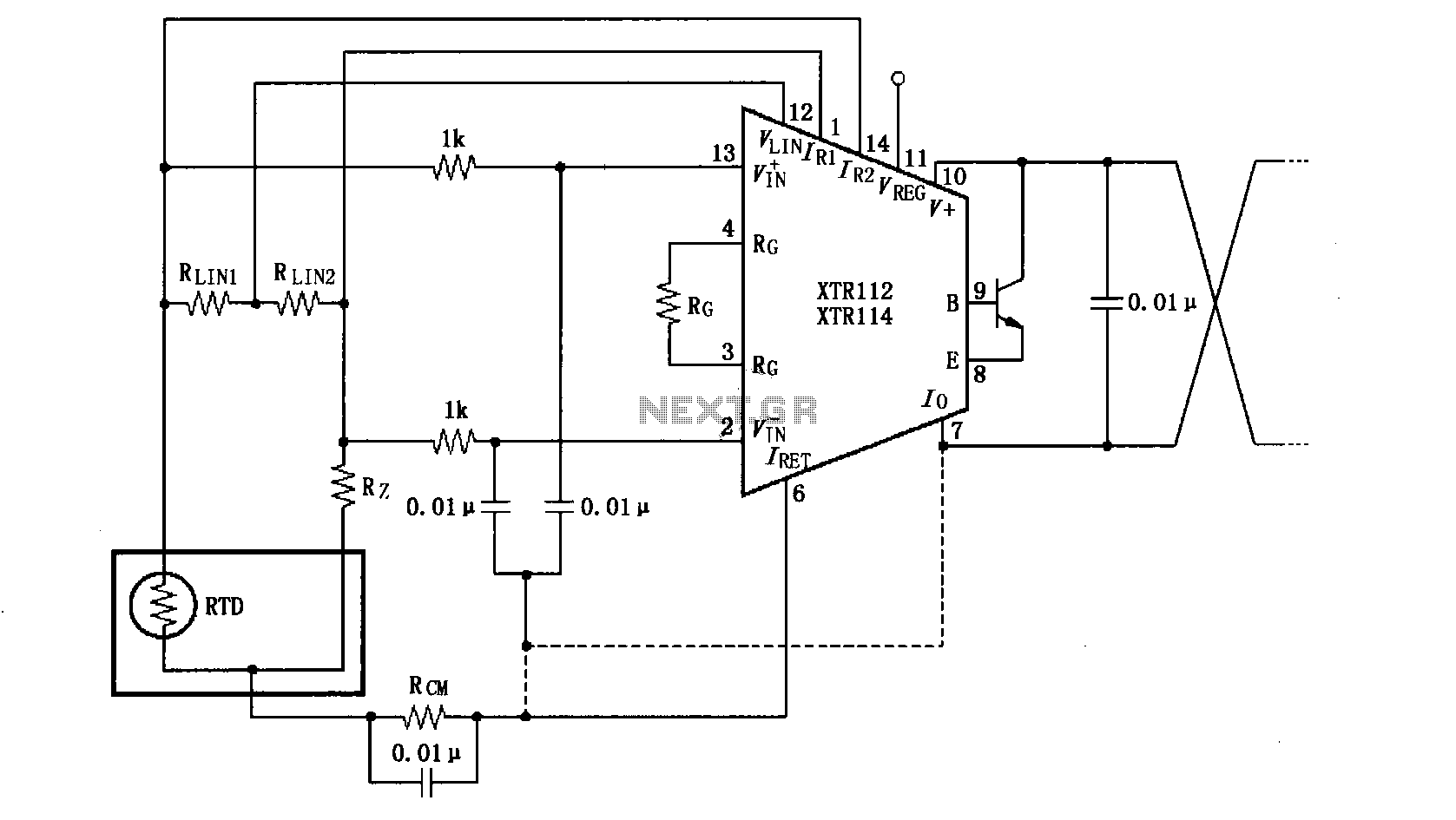
The length of the transmission wire in a current loop circuit can introduce radio frequency (RF) interference. This RF energy may lead to input errors in sensitive devices such as the XT112/114, causing instability in loop current or input...
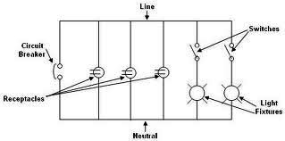
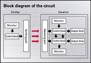
Each component of the circuit is represented in a simple block form with corresponding labels for identification, using no special symbols or language. The interconnections between these components are depicted by solid lines. The block diagrams can be read...
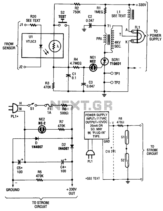
The circuit is activated by an LED/photoresistor isolator (U1), which combines a light-dependent resistor (LDR) and an LED in a single package. This device was selected for its high isolation characteristic of 2000 V, which is essential since the...