
Linearized input bypass circuit XTR112

In a current loop circuit, RF interference poses significant challenges, particularly for sensitive components like the XT112/114. The RF energy can distort the signal integrity, leading to erroneous readings and unstable performance in loop current measurements. This issue is further complicated when the RTD sensor is placed far from the XTR112/114, as the increased distance can amplify the susceptibility to interference.
To effectively combat these issues, the implementation of a 0.01 µF bypass capacitor at the input stage is crucial. This capacitor acts as a low-pass filter, allowing the desired DC signal to pass through while shunting high-frequency noise to ground. The positioning of this capacitor is vital; it should be connected to the IRET end, which, despite not being at zero volts, functions as the ground reference for the transmitter.
Moreover, attention should be given to the termination of the V+ and Io lines with another 0.01 µF capacitor. This additional filtering at the output stage further mitigates the risk of interference affecting the transmitted signal. By ensuring that both input and output lines are adequately filtered, the overall reliability and accuracy of the current loop circuit can be significantly enhanced, providing a more stable operational environment for sensitive measurements.
In summary, careful consideration of component placement and the use of bypass capacitors at strategic points within the circuit are essential measures for minimizing RF interference in current loop applications.As shown, the length of the transmission wire current loop circuit will introduce a radio frequency (RF) interference, RF energy can cause sensitive XT11l2 / 114 input errors, performance in an unstable loop current or input line current. If the RTD sensor in the distance, then input XTR112 / 114 will introduce interference. If the transmitter and sensor short connections, the more interference from the current loop cable. The method is to eliminate the interference at the input plus 0.01 F bypass capacitor filter to reduce or eliminate the interference. Connect these common points with IRET end of the bypass capacitor, although IRET ends of the DC voltage is not zero, but it is the transmitter of "ground." In addition, the V + and Io is terminated with a 0.01 F capacitor, the output will help to minimize interference.
Related Circuits
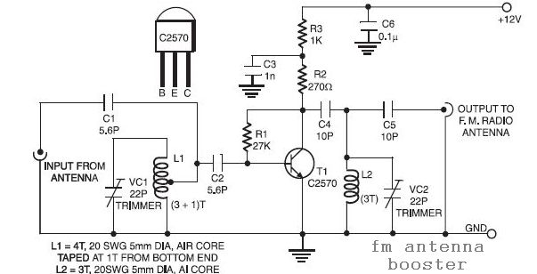
The input coil L1 is composed of four turns of 20 SWG enamelled copper wire, wound slightly spaced over a 5mm diameter former. It is tapped at the first turn from the ground lead side. Coil L2 is similar...
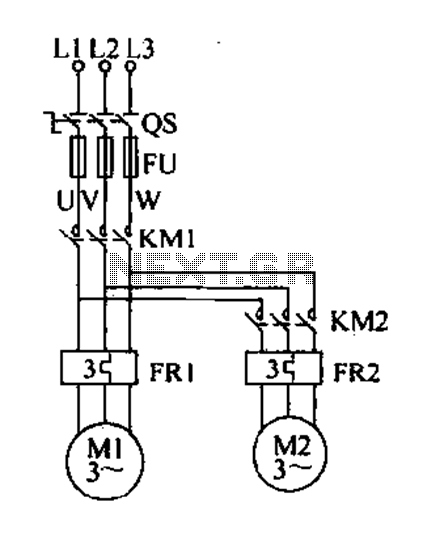
Delay starting a motor control circuit The motor control circuit designed for delayed activation incorporates a timing mechanism that ensures the motor does not start immediately upon receiving power. This is particularly useful in applications where a staggered startup...
Boiling water or cooking with a gas stove can sometimes lead to the fire being extinguished due to water spills, which can result in a significant gas overflow and pose a risk of poisoning. This example describes a stall...
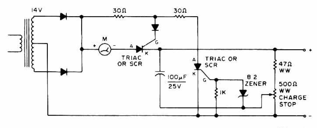
The charging circuit features adjustable voltage output settings, allowing for regulation of the charging voltage supplied to the battery. The use of a potentiometer facilitates precise voltage management, with adjustments possible down to the millivolt range. Refer to the...
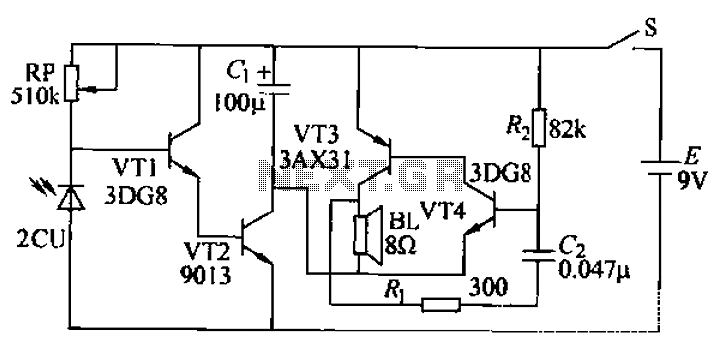
This circuit can provide various utilities, such as an alarm, door opening mechanism, or lighting control for a garden or courtyard, depending on the user's creativity. The operating principle relies on the characteristics of a photoelectric photocell, which alters...
This AC motor speed controller can handle most universal type (brushed) AC motors and other loads up to about 250W. It works in much the same way as a light dimmer circuit; by chopping part of the AC waveform...