
simple lead acid battery charger circuit design

The lead-acid battery charger circuit is designed to efficiently charge lead-acid batteries while ensuring safety and functionality. The center-tapped transformer provides the necessary voltage levels, producing a secondary output of 12V, 0V, and 12V, which allows for full-wave rectification. The two diodes are arranged in a bridge configuration to convert the alternating current (AC) from the transformer into direct current (DC), which is essential for charging the batteries.
The capacitor serves to smooth the output voltage, reducing ripple and providing a more stable charging voltage to the batteries. This is crucial for the longevity and health of lead-acid batteries, as excessive ripple can lead to gassing and damage to the battery cells.
The connection of the charger to the battery terminals must be made with care, ensuring that the positive terminal of the charger connects to the positive terminal of the battery and the negative terminal of the charger connects to the negative terminal of the battery. This correct polarity is vital to prevent damage to both the charger and the battery.
The ammeter is an important component of the circuit, providing real-time feedback on the charging process. When the batteries are in a discharged state, the ammeter will typically show a current draw between 1 and 3 amperes, indicating that the charger is actively supplying power to the batteries. As the batteries approach a fully charged state, the current will decrease, and the ammeter reading will approach zero, signaling that the charging process is complete. At this point, the charger can safely be disconnected from the accumulator, preventing overcharging and potential damage to the battery.
Overall, this simple lead-acid battery charger circuit effectively utilizes basic electronic components to provide a reliable charging solution for lead-acid batteries, ensuring proper operation and maintenance of the batteries throughout their lifecycle.For this simple lead acid battery charger we need a center tapped transformer (12V 0V 12V) which need to give a 5 amperes current, two diodes and one capacitor. To charge the batteries we need to connect the terminal + and - from the charger to the same terminals form accumulator.
When the batteries is empty the ampere-meter connected to the devic e will indicate a value between 1 and 3 amperes, if the batteries are charged the value which is indicated on ampere-meter is almost zero and the charger can be unplugged form accumulator. 🔗 External reference
Related Circuits
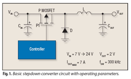
Although step-down converters, commonly known as buck converters, are highly popular, the guidelines and calculations that facilitate their design can be challenging to locate. Buck converters are a type of DC-DC converter that efficiently reduce a higher input voltage to...
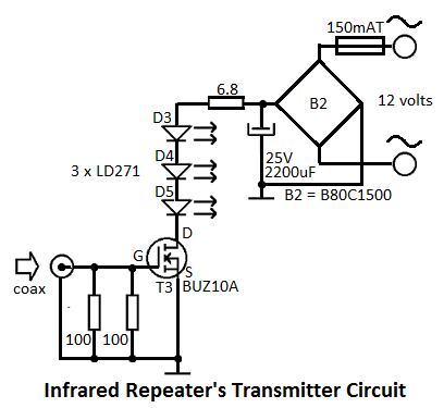
This infrared repeater system is utilized to extend the range of an infrared transmitter used with audio or video equipment up to 10 meters. The original signal is approximately. The infrared repeater system operates by receiving infrared signals from a...
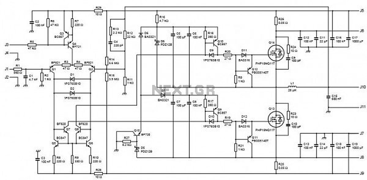
This circuit is capable of delivering approximately 200W of power output, produced by Phillips Semiconductor. It utilizes two PHP1BN11QT devices and operates with an input voltage range of 30 to 45 Volts DC. The described circuit is a high-power switching...
Using only a single transistor and a few passive components, a fairly sensitive peak detector circuit can be built. This peak detector circuit is suitable for various applications. The peak detector circuit utilizes a single transistor, typically configured in a...
This device is a combination digital clock timer and solar panel charge controller designed to maintain a deep cycle battery charged by a solar panel. The timer output controls a 12-volt load for a 32-minute interval each day. The...
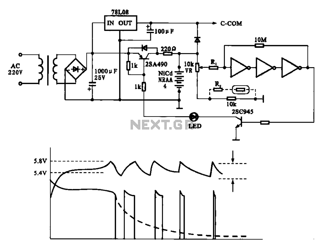
Fast charging circuit that illustrates voltage and current waveforms along with the configuration of the fast charge circuit for the charger. The detection and control circuit consists of three inverters (GMOS) from integrated circuits, enabling automatic control functions. The fast...