
Two transistor AM radio receiver circuit

The two-transistor AM radio circuit operates by utilizing a simple design that effectively amplifies and demodulates amplitude-modulated radio signals. The circuit typically employs two NPN transistors, often identified as Q1 and Q2, which serve distinct roles in the overall functionality of the radio.
The first transistor, Q1, is configured as a radio frequency (RF) amplifier. Its primary function is to amplify the weak signals received by the antenna. The input to this stage is connected to an antenna, which captures AM radio waves. The amplified output from Q1 is then fed into the base of the second transistor, Q2.
Q2 is configured as a detector or demodulator. It extracts the audio signal from the amplified RF signal. This is accomplished through a simple diode detection method, where the audio frequency component is separated from the carrier wave. The output of Q2 is then coupled to a speaker or earphone, allowing the user to hear the audio content of the radio signal.
The passive components in the circuit include resistors, capacitors, and potentially an inductor, which are used for biasing the transistors, filtering, and tuning the circuit to the desired frequency. The simplicity of the design allows for easy construction on a breadboard or printed circuit board (PCB), making it accessible for hobbyists and educational purposes.
Overall, this two-transistor AM radio circuit exemplifies an efficient and straightforward approach to radio communication, demonstrating fundamental electronic principles while providing a functional radio receiver.This two transistor AM radio circuit is also called ""mini-radio"". It uses only 2 transistors and few passive components which makes is very easy to be cons.. 🔗 External reference
Related Circuits
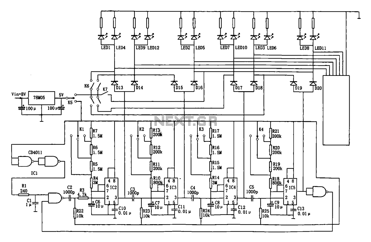
This document describes an automatic traffic intersection light control circuit. It features four monostable delay circuits, which consist of four 555 timer integrated circuits (IC2 to IC5) and several RC components interconnected. An 8V input voltage is regulated through...
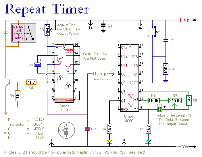
This circuit features an adjustable output timer capable of re-triggering at regular intervals. The output duration can range from a fraction of a second to over half an hour, and it can be configured to recur at regular intervals...

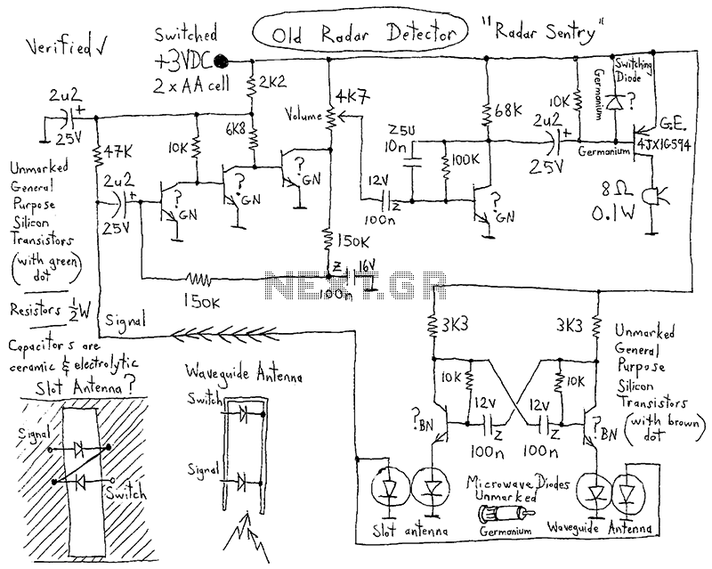
A simple X-band radar detector can indicate changes in RF radiation strength at levels as low as 2 mW/cm². When radiation strikes the detector diode, it generates a voltage at the input of an amplifier. The gain of this...
In appliances that require alternating current, NiCad (NiCd) rechargeable batteries still demonstrate significant performance advantages compared to NiMH and lithium batteries. The charger circuit is critical in handling incorrect polarity of the battery placement. The core of this battery...
Laser Command is a game developed using an 8x8 matrix LED and an Arduino Mini. It was created as a sample class project in the Gadgets, Sensors, and Activity Recognition course at Carnegie Mellon University, taught by Scott Hudson....
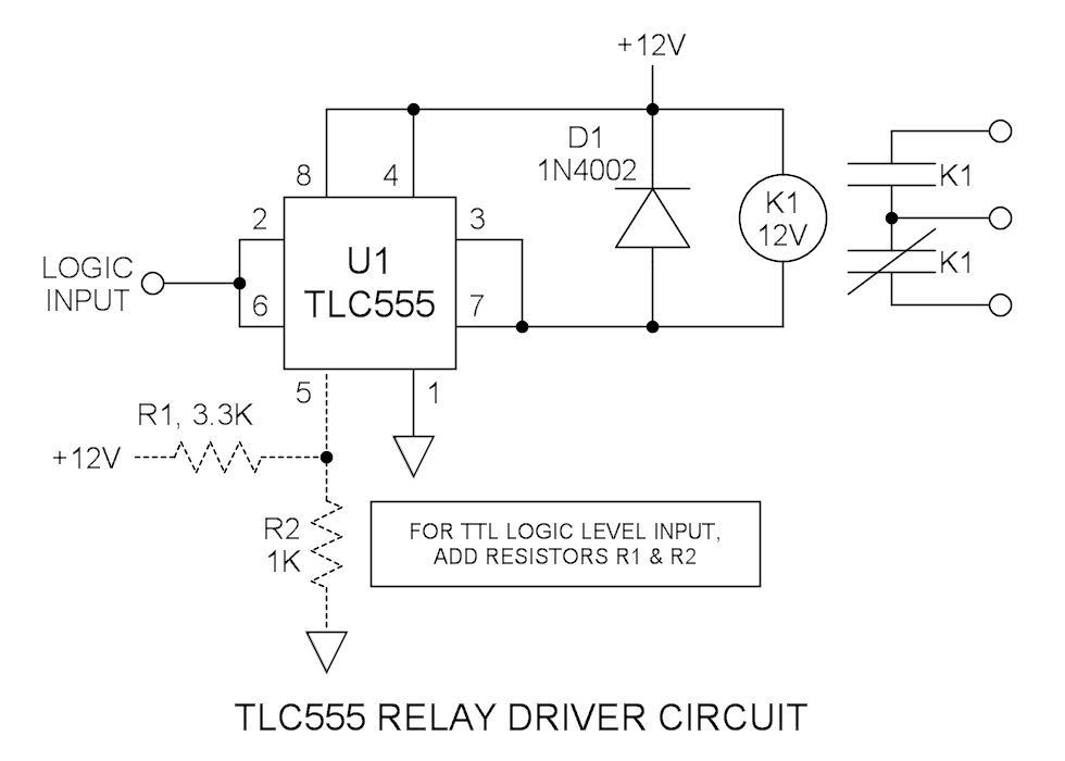
Many integrated circuits possess undocumented features or capabilities. The TLC555 output (pin 3) can sink a load of 100mA down to 1.28V. The open-drain transistor reset (pin 7) can also sink 100mA to 1V. Connecting both lines is permissible...