
Two-wire Lamp Flasher

This circuit functions as a flashing light controller for existing DC lamps operating within a voltage range of 3 to 24V. It is particularly advantageous for applications involving automotive lighting or panel indicators, where the desire is to convert a steady light into a flashing one. The circuit is designed to be inserted between the lamp and the negative supply line, effectively interrupting the current path to create the desired flashing effect.
The primary component responsible for the flashing action is a capacitor, designated as C1. The capacitance value of C1 can be adjusted from 100µF to 1000µF or even higher, allowing for customization of the flashing frequency. A larger capacitance will result in a slower flashing rate, while a smaller capacitance will produce a faster flashing rate. This flexibility enables the circuit to be tailored to specific user requirements or preferences.
In practical implementation, the circuit requires careful attention to the polarity of connections. It is crucial to respect the correct orientation when connecting the circuit to ensure proper operation and to prevent damage to the components involved. The circuit can drive lamps with a maximum power rating of up to 10W, making it suitable for a variety of lighting applications.
Overall, this flashing lamp circuit represents a simple yet effective solution for enhancing the functionality of existing lighting systems, transforming standard lamps into attention-grabbing indicators.Ideal to operate 3 to 24V DC existing on-circuit lamps LED operation is also possible. This circuit was designed to provide that continuous light lamps already wired into a circuit, become flashing. Simply insert the circuit between existing lamp and negative supply. Especially suited for car or panel pilot lights, this device can drive lamps up to 10W. * Break lamp(s) to negative supply connection(s), then insert the circuit between existing lamp(s) connection(s) and negative supply (respecting polarities!). * C1 value can be varied from 100 to 1000µF or higher, in order to change flashing frequ 🔗 External reference
Related Circuits

The circuit operates based on the principle that neon tubes N1, N2, and the photosensitive resistor RG1 form an optocoupler. When a finger touches the metal sheet S1, N1 lights up, causing RG1's resistance to decrease. This reduction allows...
The F71T12 100 W bi-pin lamp is commonly used in tanning beds. It contains mercury, as indicated by the (Hg) symbol, which is now a requirement on all fluorescent lamps containing mercury in the United States. The lamp features...
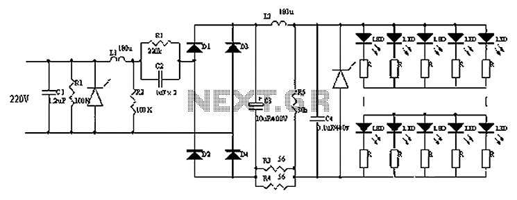
Circuits C1, R1, varistors, L1, and R2 form a filter circuit that includes a primary power supply capable of filtering out transient overvoltage inputs. The circuit also consists of C2 and R2, with additional components C3, C4, and L2....

A delay lamp circuit is ideal for bedside tables, featuring a button (SB) that turns the light on and off. If the button is not pressed, the circuit maintains a delay before the light turns off. If the light...

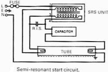
This circuit provides a simple and effective method for driving fluorescent lamps using a 12 V power supply. The circuit consists of an oscillator, a MOSFET switch, and a step-up transformer to power the fluorescent lamp. The TLC 555...
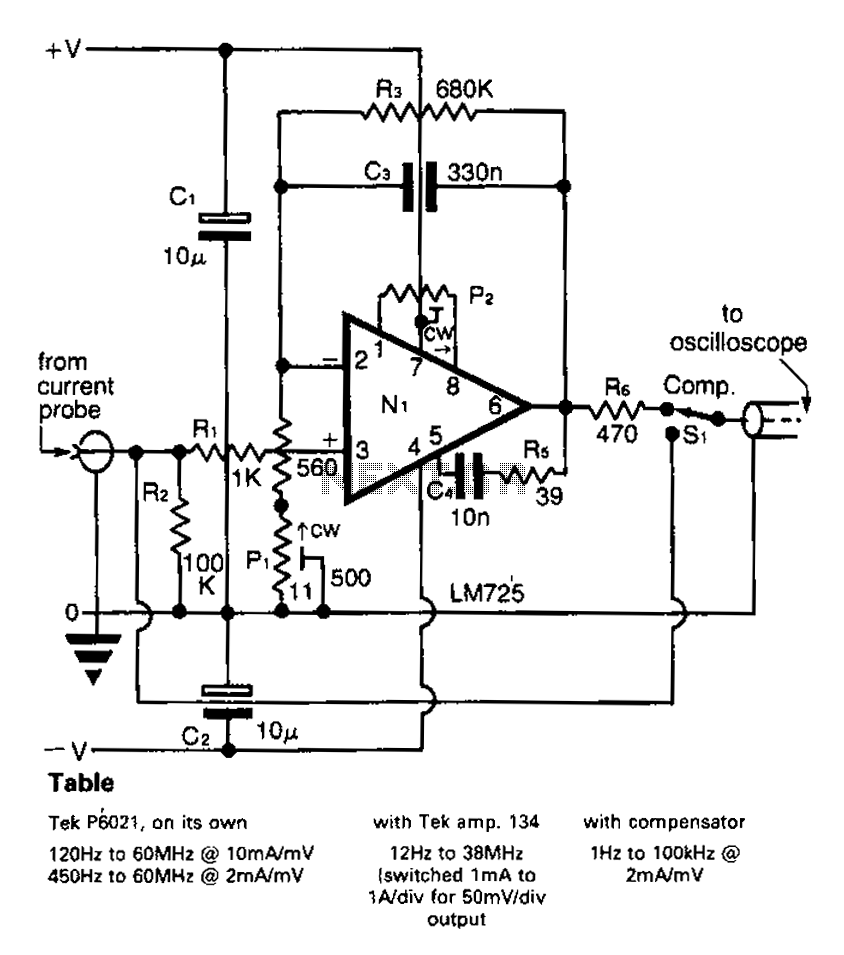
A clip-on current probe, like the Tektronix P6021, is a valuable tool for displaying current waveforms on an oscilloscope. However, it has limitations in low-frequency response. Specifically, the P6021 is sensitive to a range of 2mA/mV, and frequencies below...