
Digital delay circuit lamp circuit 3

The described delay lamp circuit is a practical solution for bedside lighting, enabling users to control the light with ease and convenience. The bistable trigger switch configuration allows for reliable operation, ensuring that the light can be turned on or off with a simple press of the button. The inverter's role is critical in maintaining the state of the light, effectively managing the delay function through the integration of resistors and capacitors.
The adjustable delay time feature is particularly beneficial, as it allows users to customize the duration for which the light remains on after being activated. This is achieved by varying the resistance values in the circuit, which directly influences the time constant defined by the RC time constant formula. The stability of the circuit is further enhanced by the use of a rectifier circuit, which converts the AC input to a stable DC output, ensuring consistent performance regardless of fluctuations in the power supply.
In terms of component selection, the use of a 9013 NPN transistor as the driving element for the thyristor is a common practice, as it provides adequate current handling and switching capabilities. The choice of a bidirectional thyristor (M/C9.1A4) allows for effective zero-crossing triggering, reducing electrical noise and improving the overall reliability of the circuit.
The design's simplicity, coupled with the effectiveness of the delay functionality, makes this circuit suitable for a variety of applications beyond bedside lighting, including decorative lighting and automated control systems where delayed activation is desired. The overall implementation of this delay lamp circuit exemplifies a well-thought-out approach to enhancing user experience through electronic design.A feast with enough delay lamp circuit is very suitable for use on the bedside table, which is characterized by a button SB, lights; then click the lights off; If the lights do not press the SB, the circuit is a delay time between after lantern [1 move off; if the lights go off before the connection resistance at the switch, Chan will fork up again. There r This lamp lights can delay canthus life easier, more pleasurable. Figure, an inverter [, and R-, R, and SB constitute bistable trigger switch, every time you press Ji Guan SB, inverter input H {ended level on the change again.
R., C, VD1 inverter I, composition t single steady-state delay circuit, adjusting column R. Or (1: Delay time can change the value of an inverter circuit V, f parallel use, to increase their ability to drive a diode VT1 and peripheral resistors VTH thyristor zero-crossing trigger. Mackerels road .220V AC power resistor R. buck, diode VD4, VD5 rectifier, vs stable regulated output voltage DC 6V, use for the entire circuit.
VT1 suitably 9013 type and other silicon NPN transistor, p ] .VTH available M/C9.1A4 type delete other small plastic bite bidirectional thyristor .SB for small touch switch. no special requirements other components. Q. the delay circuit theory by formula T O. 693RsC, seek, but because there are G chanting electrical factors, delay time will be increased to 30-SOmin and small.
Related Circuits

This system is compatible with 4-, 6-, or 8-cylinder automobiles. The timebase generated by IC5 functions as an oscillator that drives counter IC6, which divides the frequency by 6, 4, or 3 for 4-, 6-, or 8-cylinder engines, respectively....
The car parking sensor circuit utilizes a photodiode as the distance sensor. It measures the distance between adjacent sensors. The car parking sensor circuit employs photodiodes to detect the proximity of obstacles, enhancing parking safety and convenience. Photodiodes are semiconductor...

The circuit utilizes an integrated amplifier, resulting in a simple and compact design. The TDA4050 IC is employed, where a weak signal is received by the infrared photodiode (VD) and first passes through a transistor amplifier. The circuit is...
Q1 and Q2 create an ALL-ON ALL-OFF circuit that, when in the off state, draws negligible current. P1 initiates the circuit, activating the relay and powering the two integrated circuits (ICs). The lamp is energized through the relay switch,...
S/PDIF is an acronym for Sony /Philips Digital Interface (or Sony /Philips Digital Interconnect Format). The full specification for the S/PDIF interface consists of hardware and software, but only the hardware side will be discussed here - the software...
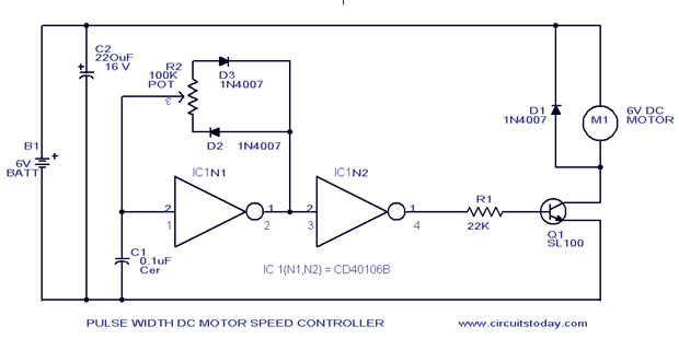
A simple PWM motor speed control circuit with a diagram and schematic for low power DC motors. This easy-to-make PWM DC motor controller is created using the IC CD40106B. The PWM (Pulse Width Modulation) motor speed control circuit utilizes the...