
Typical hardware circuit diagram of FT245BM

The FT245BM circuit is designed to facilitate USB communication by converting parallel data into a serial format. The bus-powered mode allows the device to draw power directly from the USB connection, eliminating the need for an external power supply. The power-on reset ensures that the device initializes correctly upon power-up, preventing erratic behavior.
The clock circuit is a critical component of the FT245BM, as it determines the timing for data transmission. The choice between using a dedicated 6 MHz crystal oscillator module or a discrete crystal with capacitors allows for flexibility in design, depending on available components and space constraints. The 24-pin I/O interface serves multiple functions, including data transmission and monitoring the USB bus state, which is essential for managing power consumption and ensuring efficient operation.
To enhance signal integrity and reduce electromagnetic interference, the power supply terminal is designed with a ferrite bead. This component acts as a low-pass filter, suppressing high-frequency noise that could affect the performance of the FT245BM. Additionally, decoupling and bypass capacitors are strategically placed to stabilize the power supply voltage and provide a clean power source for the device.
In PCB layout design, maintaining short and equal-length traces for data lines is paramount. This practice minimizes signal delay and skew, which can lead to data corruption. The use of the 93C46 EEPROM allows for customization of the device by enabling users to store unique identifiers and product information. This feature is particularly beneficial for applications requiring device tracking or differentiation.
If the EEPROM is omitted, the FT245BM defaults to pre-programmed values, which may suffice for simple applications but limits customization options. The ability to program the EEPROM using FTDI's software tools empowers users to tailor the device to their specific needs, thereby enhancing its functionality in various applications.FT245BM typical hardware circuit as shown in FIG. This circuit uses bus-powered mode, while using power-on reset mode, the output by the reset the device. The clock circuit can be 4 feet of 6 MHz crystal oscillator module or by the one 6 MHz crystal and two 33 pF capacitor components. Feet and I/O 24 pin connected for determining USB bus is in a suspended state or normal state. Power supply terminal in USB interface uses a bead to reduce interference and a host device; at the same time, increase the supply side decoupling and bypass capacitors, in order to improve anti-jamming performance of the circuit.
In the PCB board design, the data line traces should be as short and of equal length. Figure 3 93C46 (93C56 or 93C66) is a EEPROM, for VID, PID, serial number, and some descriptive text and other storage products. These require the user to write, to write applications provided by FTDI. Users only need to run the corresponding VB application, write the appropriate information to their own.
The EEPROM is optional. If no EEPROM, FT245BM will use the default VID, PID, product descriptors and Power Descriptor, and no serial number of the device.
Related Circuits
The metal detector circuit is shown here that the limits represent the sake of simplicity for a metal detector, but the design works remarkably well. It only uses 40,106 Hex Schmitt inverter IC, a capacitor and a search coil...
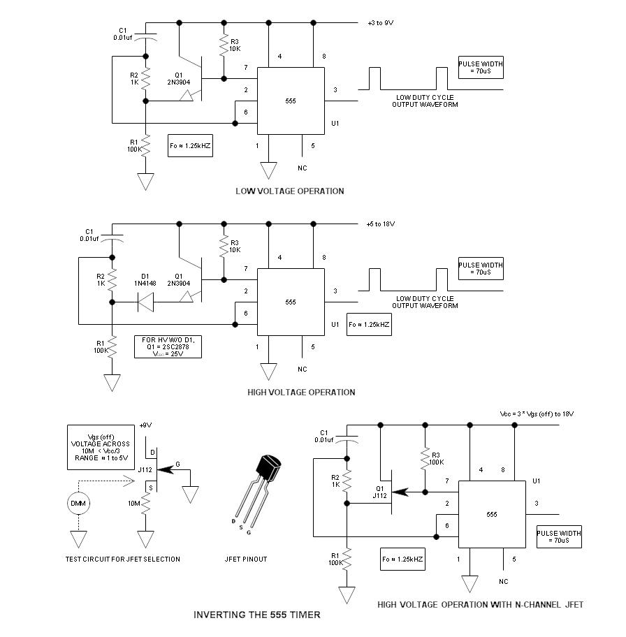
When using the 555 timer, the output polarity often appears to be incorrect, as the 555 typically cannot produce a duty cycle of less than 50%. This inverted 555 circuit is capable of generating duty cycles below 50%. The...
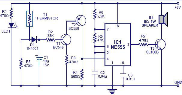
Equipment designed to detect changes associated with fire, monitor the integrity of their operations, and provide automatic control and transmission of information necessary to prepare the facility for fire, temperature, and light based on a predetermined sequence. The panel...
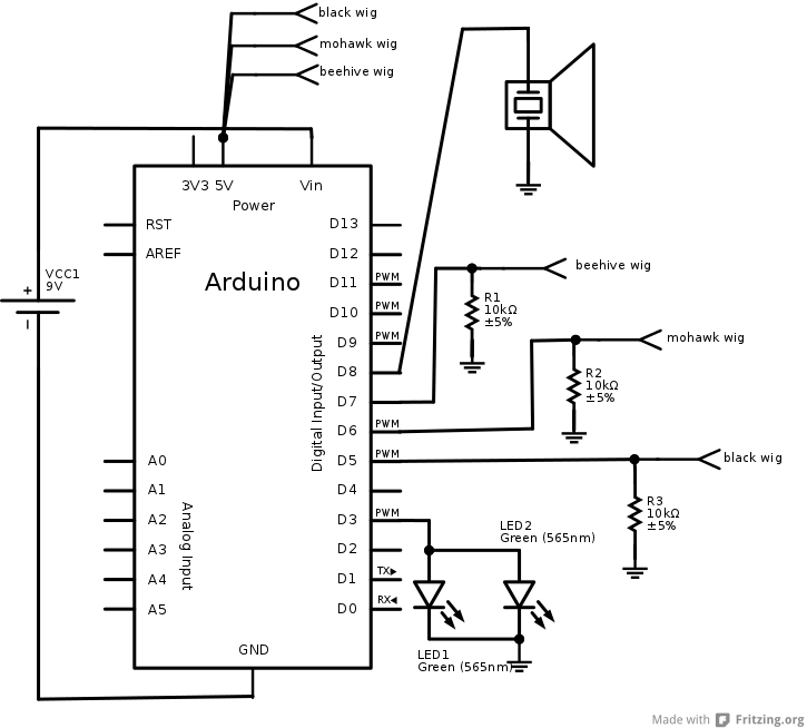
The interaction design for the singing pig was to have a different song start playing when a different wig is placed on the pig. The pig needed to stand by itself without being connected to anything else, and the...
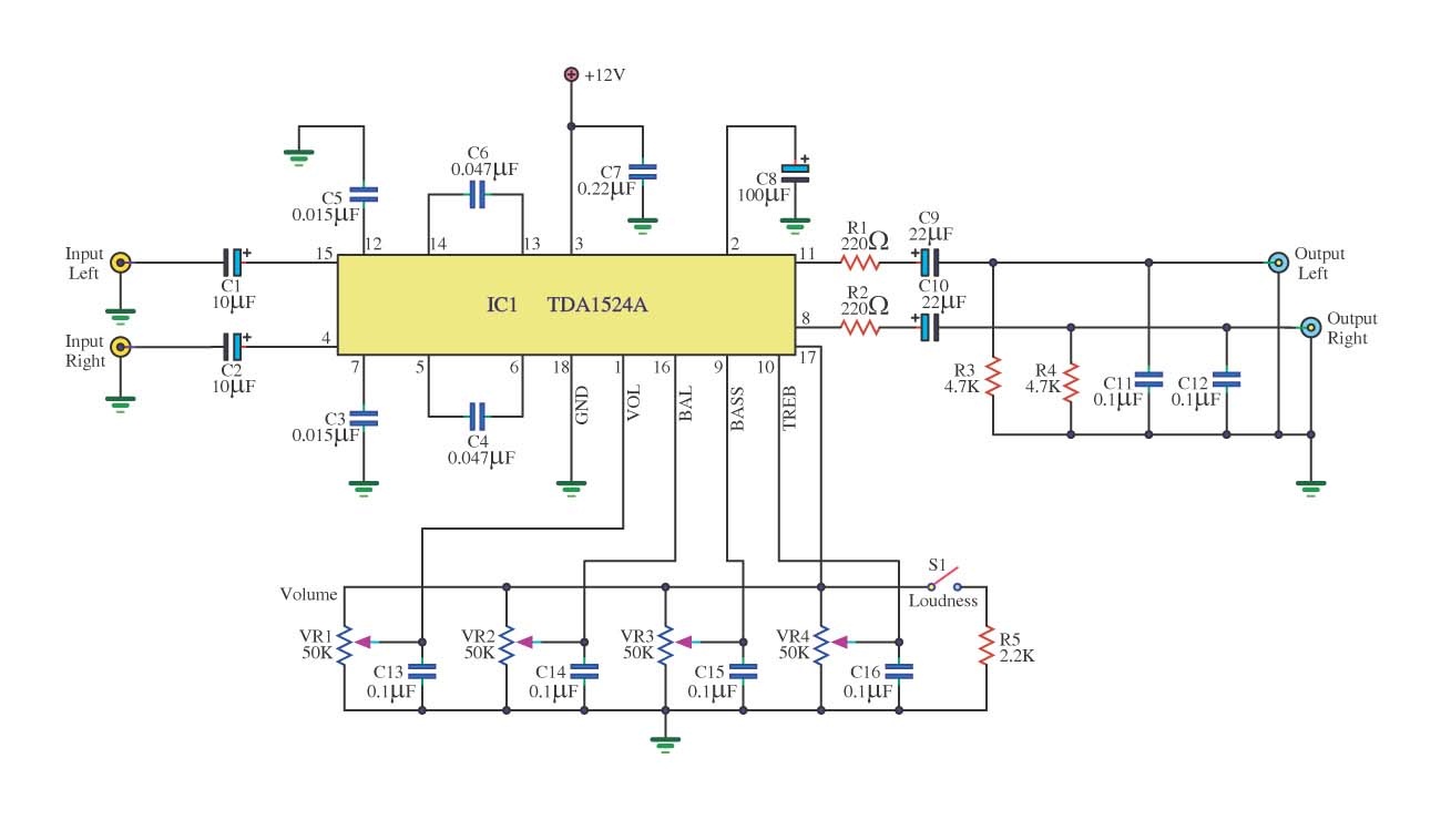
This is a simple tone control circuit using the TDA1524A, which is a key component in this IC chip diagram from Philips. The circuit allows for tone control adjustments such as bass, treble, and balance, enabling users to fine-tune...
This electronic clock comprises the LM8365 and the LDD640R displays. The LM8365 can show the hour/minute and month/day. Users can set two alarm outputs, AD1 and AD2, by pressing either the 12h or 24h button. The operating voltage range...