
UC3625 brushless DC motor open loop speed control

The brushless DC motor driving circuit is configured to operate efficiently at a voltage of 45V and a maximum current of 8A. The use of an external potentiometer for PWM duty cycle adjustment allows for precise control of the motor speed, making it suitable for applications requiring variable speed operation. The three-phase bridge configuration is essential for driving the motor, where P-channel and N-channel MOSFETs are strategically placed to handle the switching of current through the motor windings.
The inclusion of current sensing resistors is critical for monitoring the motor's performance and ensuring safe operation. These resistors provide feedback for current regulation, allowing the circuit to maintain desired performance levels while preventing overcurrent conditions. The four-quadrant operation capability is a significant feature, enabling the motor to not only drive forward and reverse but also to brake effectively. This is accomplished by controlling the direction of current flow through the motor windings, which is essential for applications such as robotics and electric vehicles.
In summary, this brushless DC motor driving circuit is designed for high efficiency and versatility, with features that support speed control, current monitoring, and braking functionality. Its robust design, leveraging modern MOSFET technology, ensures reliable performance in demanding applications.28 is 45V/8A brushless DC motor driving circuit diagram. It is an open voltage-controlled, adjustable by one pin external potentiometer adjustment of the PWM duty cycle, the av erage voltage supplied to the motor control to adjust the speed. Table figure only shows the way to a three-phase bridge by 16 feet (PUC) and 12 feet (PDC) are driven P-channel and N-channel MOSFET. Rejection two current sensing resistor RT and helmet, so the circuit can operate in four-quadrant mode, the brake can be controlled, and an average current control system.
Related Circuits
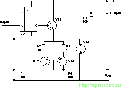
This voltage-controlled frequency divider circuit produces lower frequency pulses that depend on the control voltage, with synchronous rising edges for the input and output pulses. Typically, such frequency dividers utilize a monostable circuit connected between an inverted output and...
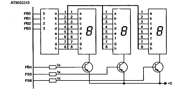
LED displays consist of arrays of Light Emitting Diodes (LEDs) arranged in various shapes to convey specific information. The operation of LED displays is similar to that of standard LEDs, requiring straightforward connections when sufficient microcontroller pins are available....
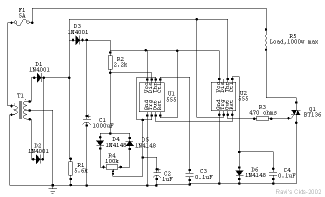
The circuit is built around two 555 timer ICs, U1 and U2. U1 is configured as a variable duty cycle oscillator with a constant time period of approximately 0.1 seconds. The duty cycle can be adjusted from 0 to...
The circuit illustrated in Figure 2-50 utilizes a field effect tube and a combination of electronic components to create a unique self-lighting controller. The working lamp remains illuminated at a reduced brightness rather than being completely turned off, which...
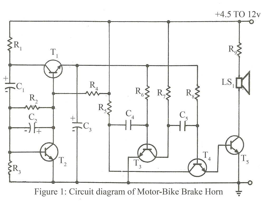
The circuit is designed to operate within a voltage range of 4.5V to 12V DC, or it can be directly connected to the brake point of a motorcycle. Resistor R7 should be replaced with a 1-ohm, 1/2W resistor when...
PicCon is a PIC microcontroller based radio controller designed for hidden transmitter hunting. When combined with a radio transmitter, it will produce tone sequences and Morse code messages at user-programmed times. It is completely field programmable via DTMF tones,...