
Ultra-Sonic Ranging Design

The described circuit employs a straightforward yet effective design for ultrasonic distance measurement, leveraging low-cost components to achieve reliable performance. The use of a PIC12C508 microcontroller ensures efficient control of the ultrasonic transducer, while the MAX232 provides the necessary drive voltage for optimal performance. The dual-stage operational amplifier configuration allows for significant amplification of the received signal, enhancing sensitivity to echoes, particularly at close range. The integration of hysteresis in the comparator stage aids in eliminating false triggers, ensuring accurate distance readings. The design effectively addresses the challenges posed by direct coupling and mechanical ringing, implementing a robust threshold adjustment strategy to differentiate between valid echoes and spurious signals. Overall, this circuit design exemplifies an effective balance between cost, complexity, and functionality, making it suitable for applications in robotic vision systems and other distance-sensing tasks.The module costs GB38. 00 and the transducer costs a further GB17. 00. In fairness, the Polaroid module does the job it was intended to do, which requires the range, but that job is not to provide the eyes of a small robot. The circuit is designed to be low cost. It uses a PIC12C508 to perform the control func tions and standard 40khz piezo transducers. The drive to the transmitting transducer could be simplest driven directly from the PIC. The 5v drive can give a useful range for large objects, but can be problematic detecting smaller objects. The transducer can handle 20v of drive, so I decided to get up close to this level. A MAX232 IC, usually used for RS232 communication makes and ideal driver, providing about 16v of drive.
The receiver is a classic two stage op-amp circuit. The input capacitor C8 blocks some residual DC which always seems to be present. Each gain stage is set to 24 for a total gain of 576-ish. This is close the 25 maximum gain available using the LM1458. The gain bandwidth product for the LM1458 is 1Mhz. The maximum gain at 40khz is 1000000/40000 = 25. The output of the amplifier is fed into an LM311 comparator. A small amount of positive feedback provides some hysterisis to give a clean stable output. The problem of getting operation down to 1-2cm is that the receiver will pick up direct coupling from the transmitter, which is right next to it. To make matters worse the piezo transducer is a mechanical object that keeps resonating some time after the drive has been removed.
Up to 1mS depending on when you decide it has stopped. It is much harder to tell the difference between this direct coupled ringing and a returning echo, which is why many designs, including the Polaroid module, simply blank out this period. Looking at the returning echo on an oscilloscope shows that it is much larger in magnitude at close quarters than the cross-coupled signal.
I therefore adjust the detection threshold during this time so that only the echo is detectable. The 100n capacitor C10 is charged to about –6v during the burst. This discharges quite quickly through the 10k resistor R6 to restore sensitivity for more distant echo ’s. A convenient negative voltage for the op-amp and comparator is generated by the MAX232. Unfortunately, this also generates quite a bit of high frequency noise. I therefore shut it down whilst listening for the echo. The 10uF capacitor C9 holds the negative rail just long enough to do this. In operation, the processor waits for an active low trigger pulse to come in. It then generates just eight cycles of 40khz. The echo line is then raised to signal the host processor to start timing. The raising of the echo line also shuts of the MAX232. After a while – no more than 10-12mS normally, the returning echo will be detected and the PIC will lower the echo line.
The width of this pulse represents the flight time of the sonic burst. If no echo is detected then it will automatically time out after about 30mS (Its two times the WDT period of the PIC). Because the MAX232 is shut down during echo detection, you must wait at least 10mS between measurement cycles for the +/- 10v to recharge.
Performance of this design is, I think, quite good. It will reliably measure down to 3cm and will continue detecting down to 1cm or less but after 2-3cm the pulse width doesn ’t get any smaller. 🔗 External reference
Related Circuits
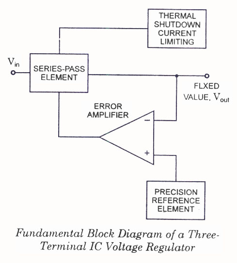
IC Voltage Regulators - Circuit diagram and block diagram of linear, fixed, adjustable (positive and negative), and switching voltage regulators. IC voltage regulators are essential components in electronic circuits, providing stable output voltages from a varying input voltage source. They...
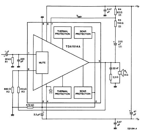
The TDA1514 audio amplifier circuit design is an electronic project capable of delivering high audio power output using a specialized audio integrated circuit (IC) and a few common components. Manufactured by Philips Semiconductor, the TDA1514 audio IC can provide...
This document discusses the advantages and disadvantages of various power supply technologies, along with the design considerations necessary for selecting and evaluating a mains transformer. It covers the pros and cons of external supplies, inrush current control, RF emissions...
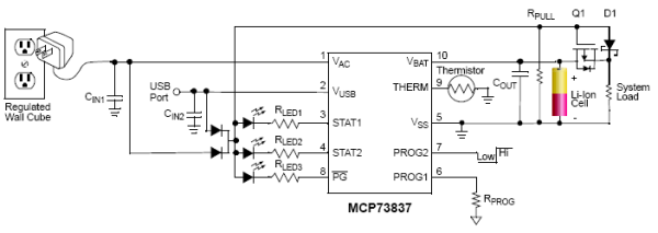
Designing a Li-Ion Battery Charger with Load Sharing MCP73837. Batteries frequently serve as the primary energy source for portable electronic devices. Although these devices rely on batteries, portable consumer electronics such as GPS devices and multimedia players often draw...
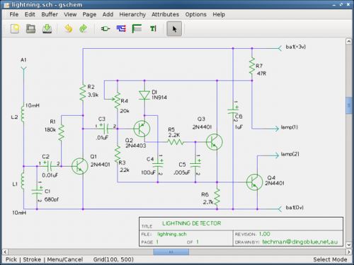
Are you looking for a free schematic and PCB design tool? The gEDA project has produced and continues to work on a complete GPL licensed suite and toolkit for electronic design. The gEDA project offers a comprehensive suite of tools...
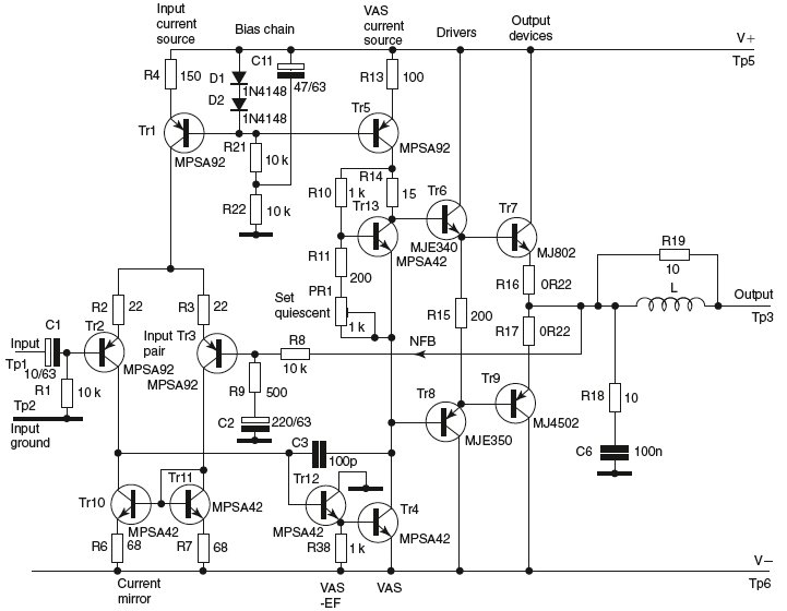
The more one understands about any subject, the more interesting it becomes. As this article is read, it will be found that the subject of... A comprehensive electronic schematic typically involves various components, each serving a specific function in the...