
Ultrasonic distance finder circuit

The ultrasonic distance meter operates on the principle that sound waves, including ultrasound, have a known velocity in air. The time taken for the sound wave to travel to a target and back can be used to determine the distance. The emitted ultrasonic wave triggers a pulse generator that counts the time taken for the wave to return. The circuit includes a transmitter, receiver, a counter with a digital display, and an oscillator that is activated by the transmitted and received signals.
The schematic diagram of the circuit consists of a transmitter with gates N1 and N2 forming a bridge circuit. The ultrasonic transducer US1 is connected between the outputs to generate an alternating peak-to-peak voltage of 18 V. The oscillator, driven by N1 and N3, operates at a frequency determined by resistor R1, typically set near 40 kHz for maximum efficiency. The receiver amplifies the signal captured by the transducer US2 using two transistor stages (T5 and T6). A threshold detector (T7) activates when the voltage at its base falls below a certain level, allowing the circuit to process the received signal.
An additional oscillator is built around IC3, which divides the frequency to achieve a setting of 17190 Hz, correlating to the speed of sound in air at 20°C. A digital voltmeter (IC1) displays the measured distance in centimeters. The counter is reset with each pulse from the oscillator, allowing for continuous distance measurements. The circuit can take new measurements every second.
Important operational details include managing the timing between the transmitted and received signals to avoid interference. The circuit is designed to prevent immediate cutoff of the counting process by ensuring that the reset state of the flip-flop (FF1) is maintained until the transmission period is complete. This design limitation results in a minimum measurable distance of 35 cm. The absence of automatic gain control (AGC) or error detection simplifies the circuit but may affect measurement accuracy.
Construction considerations suggest that the counter and pointer stages can be built separately, with careful attention to connections and component placement to minimize interference. A 9V battery is recommended for stable operation, as the circuit draws approximately 250 mA. Testing the circuit can be performed without an oscilloscope by checking the output at specific points and ensuring proper operation of the oscillator and receiver.
The final assembly involves calibrating the circuit for accurate distance readings, with adjustments made to the potentiometers to ensure correct display values at various distances. The circuit can achieve a precision of ±1 cm for distances up to 7-8 meters, with performance influenced by environmental factors such as temperature and humidity. Expanding the measurement range can be achieved by enhancing the receiver's amplification or the transmitter's output voltage.
Components used in the circuit include a variety of resistors, capacitors, transistors, and integrated circuits, each selected for their specific roles in signal processing and measurement. The ultrasonic transducers (US1 and US2) are critical for the emission and reception of the ultrasonic waves, while the digital display provides a user-friendly interface for reading the measured distances.The circuit described here uses ultrasonic oscillations and operates based on the propagation velocity of these oscillations in the air. Thus, we can easily determine the distance of two points if the time within which the wave travels this distance is measured.
There are three main categories of distance measurement methods in use: a) By mechanical means. b) By optical means. and c) By electronic means. Almost all methods are based on some form of radiation such as radio waves, light, sound, or infrared radiation. Given the propagation rates of these radiations, distance measurement is a matter of determining the wave transition time from one point to another.
Infrared radiation is mainly used for long distances (in the order of a few kilometers) since it is relatively easy to form. For distances over 100 km, electronic devices are used, but their effectiveness is influenced by factors such as atmospheric conditions and visibility.
With the advancement of space technology, laser systems have been used in conjunction with electro-optical systems to determine the terrestrial and off-shore of artificial satellites.
The ultrasonic distance meter
The sounds, ultrasounds and other known frequency fluctuations have a certain known propagation velocity in the air. Therefore, the time required to propagate the distance between the target transmitter and vice versa can be used to determine the distance.
The emitted wave gives a start pulse to a numerator running at the same frequency as the propagation velocity in cm / sec. The signal received by the reflection provides the expiration pulse. In this way, the numerator gives the distance that the wave has spread. Of course, it is necessary to reduce the distance of the distance since we only want the transition distance.
The following figure shows what we have described in a functional chart. Transmitter, receiver, numerator with digital pointer and oscillator that is excited or interrupted by the transmitted and received pulses.

The schematic diagram of the circuit
The transmitter consists of the gates N1 and N2 which form a bridge circuit. The US1 ultrasonic converter is connected between the 2-port outputs to ensure an alternating peak-to-peak voltage of 18 V between them (with 9V supply).
N1 also works as an oscillator stimulated and de-stimulated by N3. Its frequency is determined by R1 and depends on the type of inverter used. In this construction, a 40 kHz TCO is used, but others can work satisfactorily.
The frequency of the oscillator is set to R1 as near as possible to 40kHz because this is the maximum efficiency frequency of the inverter. The receiver is very simple due to the experimental character of the circuit.
Two successive common transmitter circuits (T5, T6) amplify the signal received by the US2.
T7 acts as a threshold detector as it runs when the voltage at its base is less than the supply (-6V), i.e. T7 is when the alternating voltage in the P2 rotor is greater than 1.2V from peak to peak
One more oscillator is around IC3 (R17, R18, P3 and C9).
IC3 is mainly a 2-14 divisor with a built-in oscillator. The frequency is set at 17190Hz with P3, since the sound velocity in the air is 343.8m / sec at 20, C = (34380cm / sec) / 2 = 17190. A 2.5-digit digital voltmeter is placed in place of a numerator. IC1 directly leads the markers Dp2 to Dp4, which are interconnected to IC1 with the transistor T2 to T4.
IC2 supplies with the stabilized voltage 5V the counter section and the circuit indicators.
IC1 has the ability to drive 4 pointers but it does not need more than 3. Nearly all other components are used to synchronize the various stages. This mainly indicates the preset pulse and frequency variations at different points in the circuit. With an oscillator frequency of 17190 Hz, output Q14 of IC3 will have a signal frequency of 1Hz. (17190: 2-14). This output is connected to the reset input by the N7 inverter and a second monodonator (N8, R20, C11). With the arrival of a negative pulse face at Q14, a short pulse occurs at ICI input 5. Instead, a positive pulse front at Q14 gives a short pulse at the repositioning input. The signal from Q14 is inverted by N7 and is driven into two further monodonts: one to drive the transmitter (N3, R10, C5) and one connected to the FF1 flap re-positioning input.
The clock timing input of FF1 is connected to T7 and output Q to N5.
Therefore, IC1 receives a resetting pulse with each positive pulse arrival arrival at the Q14 output of IC3 which automatically cancels the counter. At the same time, the monovodule is activated around N3 (with a negative pulse front at the N7 output) allowing the oscillator to emit a signal over 0.3 msec.
During this time US1 emits about 12 pulses (40Hz) which are then reflected by the target and received by US2. At the same time as the ultrasonic signal is emitted, FF1 is repositioned and retained by the N4 monolar (nearly 2msec).
The output Q then comes to a logical state "1", and the signal from the 17190Hz oscillator is led to the IC1 counter via N5. Once the amplified reception signal reaches the clock input of FF1, output Q goes to a logical "0" state and N5 blocks the IC1 counter input.
At that moment the counter has measured the actual distance in centimeters. N6 activates the latch, advancing to it the contents of the counter which are then displayed by the pointers. The counter is reset from the next positive pulse front to Q14, allowing a new measurement to be obtained.
The previous mark is assembled until the arrival of information for a new measurement. The whole layout has the ability to take new measurements every second.
Let us now see some necessary details on circuit operation. The US2 converter is natural to capture the transmitted signal immediately unless we do something to avoid it.
If we do not avoid it, the counter will be cut off immediately and we will not be able to count. This problem is solved if we assure such conditions that the residence time in the constant state of N4 is sufficiently greater than the time required for the emission of the magnitude (2 msec).
During this time, the floppy flop remains in the reset state irrespective of the presence or absence of a signal at the clock input. After 2 ms, FF1 is released so that the direct signal is not confused with the reflected signal. The only downside to this delay is the failure to measure distances of less than 35 cm. The circuit does not include an AGC rating or an automatic error detector for the sake of simplicity.
Construction
Counter and pointer stages can be constructed separately.
Note that one end of R8 is connected to the dotting point of Dp2 while the other one to the ground. We recommend using neroboard for the rest of the circuit. Ensure that the connection cables are small, and that there is a separation between the receiving step and the transmission stage. The two inverters are placed side by side without touching, and facing in the same direction. Prefer 9V batteries because the power supply may create instability. Consumption is rather high, of 250 mA, which can not be avoided by using LED indicators. However, the batteries are not depleted quickly because the circuit is only used for a few seconds at a time.
An operating test can be done without the use of an oscillograph. Simply disconnect the connection between N5 and clock and connect the second to terminal 4 of the IC3. (output Q8). On the pointer you must read "128". When the clock input is shorted to the ground, the display must be "000". This is the way to test both the IC3 and the oscillator. The broadcast is easily controlled by listening to US1. Although the 40kHz signal is not heard, the output of each waveform sounds like a "click" every second.
The receiver test is not easy, but the presence of a 4.5V DC voltage on the T5 and T6 collectors is a sign of normal operation.
Once this is done, the whole circuit can be set and controlled. Turn the P2 cursor to the maximum and mark the mark. This indication is generated by the counter between 2 pulses (the latch and the reset) that are half a second apart.
It is worth bearing in mind that this will be the permanent indication in the absence of a reflection signal. Point the circuit to an object or wall one meter apart and a surface of at least one square meter perpendicular to the transmission direction.
Slowly turn P2 back to the point where you'll get a meter mark. If you do not get it and the mark is 40-60cm, you need to remove just a little bit of the two metrics and use a larger capacitor in place of C6.
Once you have set the P2 setting for 1m. you can proceed to the next step, which is to set the 40Hz frequency. With the circuit in the same position, turn P1 until some indication appears. The process continues until the indicator for any P2 setting is lost. Place the circuit at a distance of 5m from the target and reset P2 for the correct display. Finally, reattach the circuit just 3m away from the target. set P3 for exact indication and finish!
With the original circuit, we achieved very good results and precision ± cm for distances up to 7-8m.
The accuracy depends on ambient temperature, atmospheric pressure and humidity because the sound velocity is affected by these factors. The measuring range (range) of the instrument can be expanded by increasing the amplification of the receiver or the emission voltage.
If the meter is equipped with instrument length compensation, it will be able to perform wall-to-wall precision measurements.
Components
Resistors: R1-R7 = 22Ω | R8 = 270Ω | R9 = 33ΚΩ | R10 = 330ΚΩ | R11,R12,R14 = 1Μ5 | R13 = 4K7 | R15 = 470ΚΩ | R16 = 22ΚΩ | R17 = 560ΚΩ | R18 = 47ΚΩ | R19,R20 = 10ΚΩ | P1 = 10K | P2 = 4K7 | P3 = 10K
Capacitors: C1 = 10μF/10V | C3 = 100n | C4 = 1n | C5 = 820p | C6,C7 = 1n5 | C8 = 2n2 | C9 = 270p | C10,C11 = 220p | C12 = 10μF/16V | C13 = 1n
Semiconductors: T2-T4 = BC141 | T5,T6 = BC549C | T7 = BC559C | IC1 = 74C928 | IC2 = 7805 | IC3 = 4060 | IC4 = 4027 | IC5,IC6 = 4093
Other: Dp2-Dp4 = 7760(CC) | US1 = MA40L1S | US2 = MA40L1R | 9V battery | Plastic Box
Related Circuits
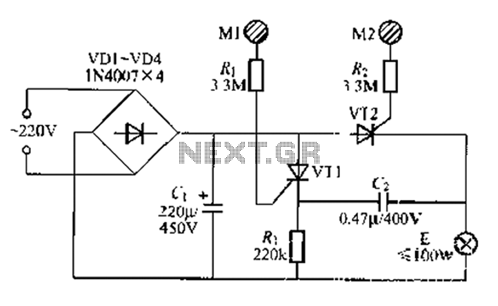
A circuit configuration features a relatively new strong key touch-state switch. Normally, the thyristors VT1 and VT2 are in the off-state, allowing minimal current to pass through the lamp F. At this point, the capacitance C comes into play....
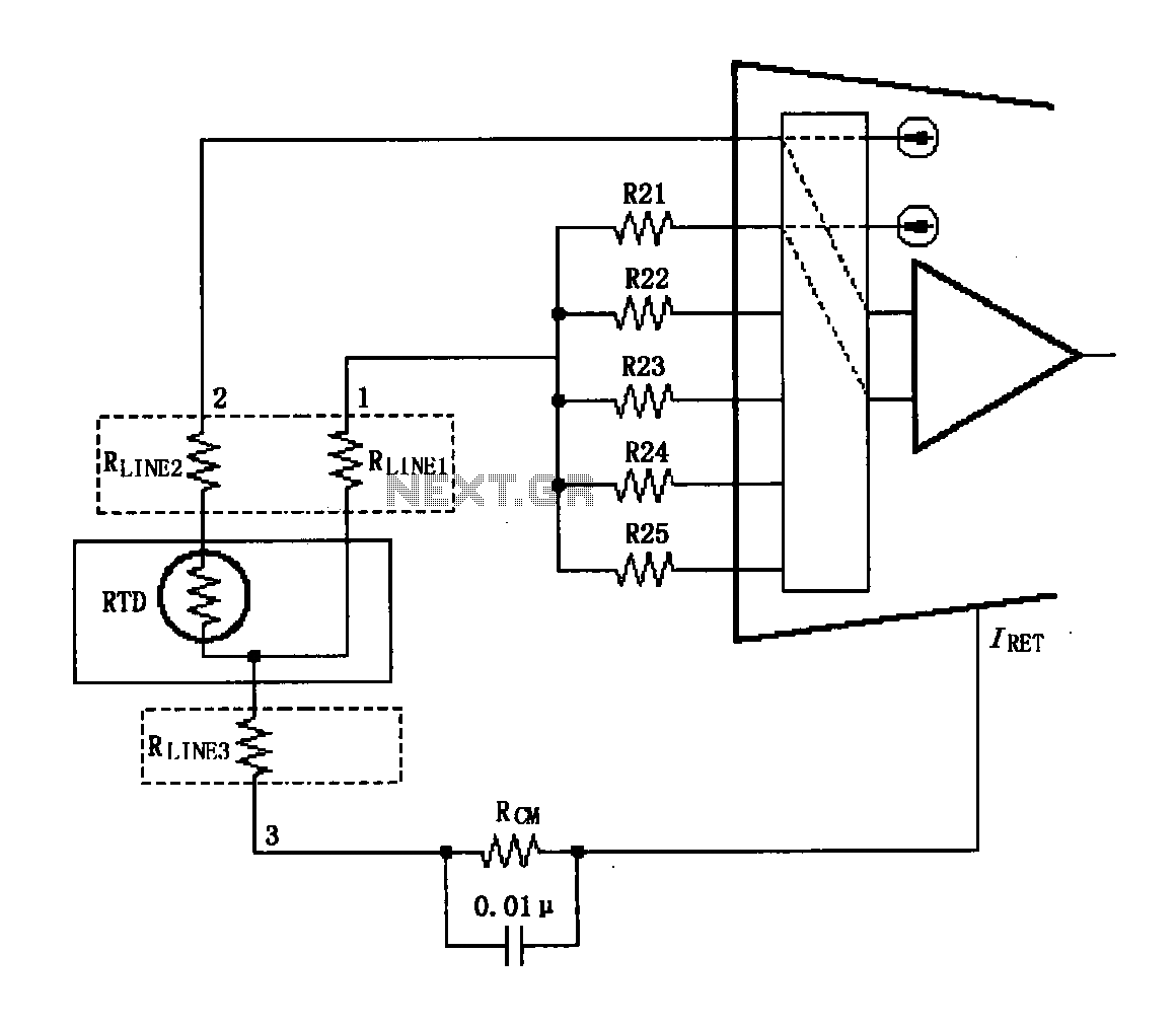
The circuit diagram illustrates the three-wire RTD connection for the XTR108. It is important to note that the lead resistance of the RTD sensor can introduce measurement errors. In the provided figure, connections "1" and "2" represent the lead...
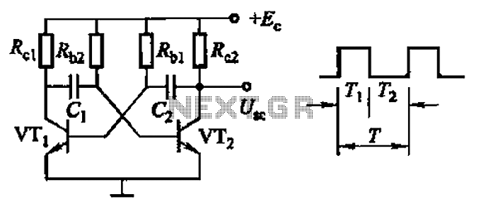
Common non-sinusoidal oscillator circuit, waveform and frequency formula - square wave oscillator - self-excited multivibrator The common non-sinusoidal oscillator circuit, specifically the square wave oscillator, is a fundamental electronic circuit utilized to generate square wave signals. It operates based on...
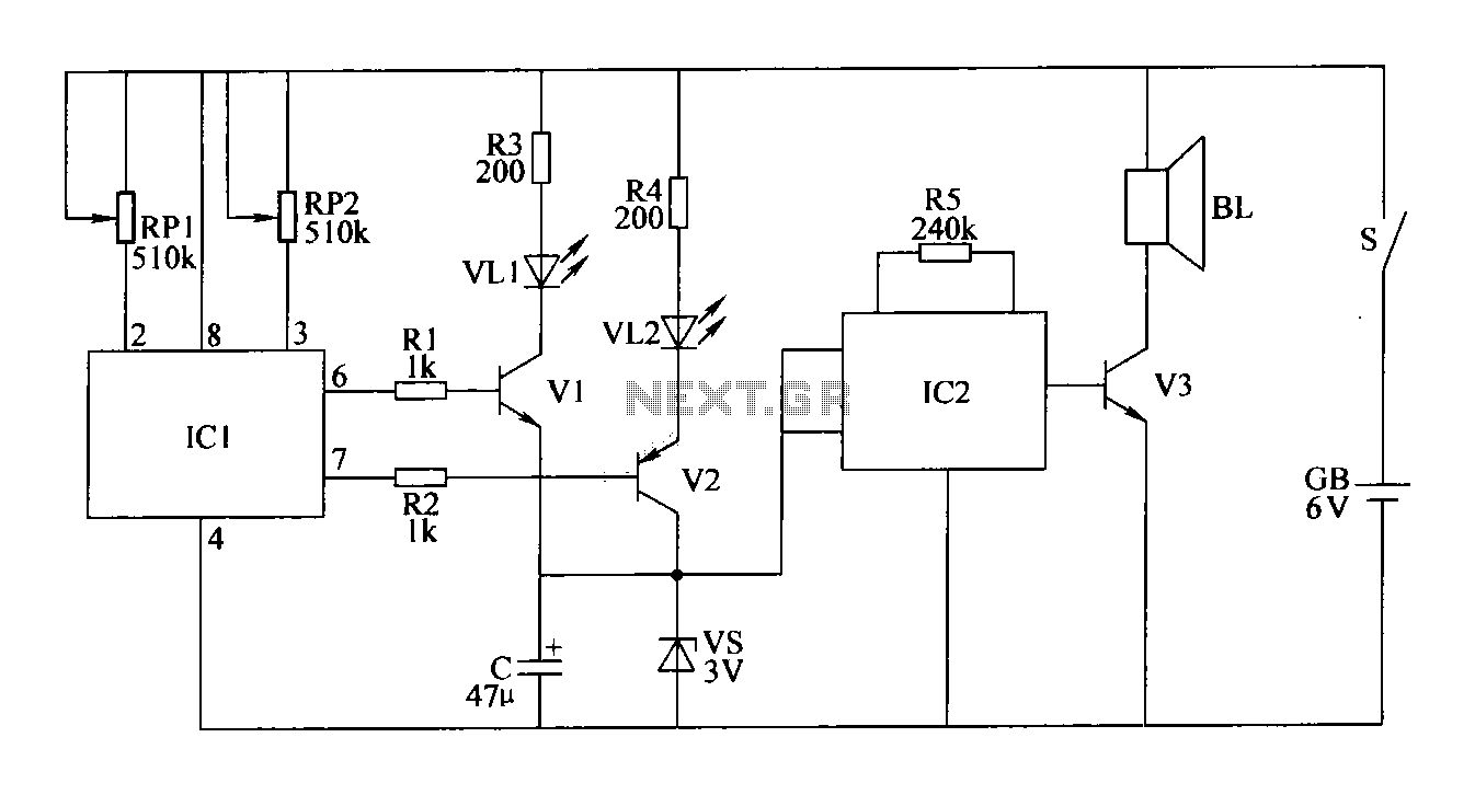
The double-limit temperature alarm circuit consists of a temperature detection control circuit, a temperature indicating circuit, and an alarm sound circuit. The components selected include resistors R1 to R5, which should be 1/4W metal film or carbon film resistors....
The circuit depicted will automatically switch ON and OFF at night and morning, respectively. In this circuit, R1 can be adjusted to change the sensitivity. The operation of the circuit is straightforward. The Light Dependent Resistor (LDR) exhibits very...
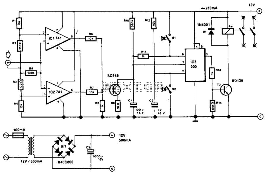
This circuit will disconnect the line supply to audio or video equipment if there has been no input signal for approximately 2 seconds. Switch SI provides manual operation, while switch S2 functions as a reset mechanism. This circuit allows...